
User's Manual

TECHNICAL DATA
17 February 2017
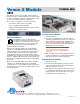
Venue 2 Module
VRT2
The Venue 2 Receiver is a modular solution that effec-
tively deals with a congested RF spectrum with a variety
of options that allows a system configuration to be ideal-
ized for a particular installation or application.
The receiver is comprised of several components:
• The master rack mount host assembly
• Up to six VRT2 receiver modules
• Built-in antenna multicoupler with loop-thru output
• Software for setup and control
iQ Front-end Filtering
TM
Each VRT2 receiver module features a
tracking front-end filter that travels across the
spectrum to stay centered on the selected
operating frequency. Under certain condi-
tions, the filter parameters change automatically to
minimize IM (intermodulation).
When the incoming RF signal is strong, the iQ filter
switches to a narrowband mode with reduced gain for
additional suppression of signals above and below the
operating frequency. This mode is especially useful
in applications such as a live stage production where
transmitters are generally close to the receiver antennas.
In these conditions, IM is prevalent, but the signals that
generate it are significantly reduced by the narrowband
filter mode.
When the incoming RF signal level weakens, the filter
switches to an extended range mode for maximum
sensitivity in the receiver module. The filter tracks in fine
incremental steps so that it is accurately centered on the
operating frequency.
Installing Receiver Modules
1. Turn the power off.
2. The receiver modules interface with the main as-
sembly through multi-pin connectors on either side
of the chassis. Insert the module straight down
and then slide it toward the main housing to insert
the connector pins. The module should sit flush
against the side of the housing.
Caution: Make sure the connectors align
correctly. Do not force the module onto
the tab. Excessive force may damage the
connectors.
3. Align the ridge on the retaining clip with the slot in
the chassis and press the clip downward until the
ridge snaps into the slot in the side panel.
Removing Receiver Modules
1. Turn the power off.
2. Remove the retaining clip by pressing on it side-
ways to release it from the slot in the side panel.
Then pull upward to remove it.
3. Pull outward on the module to release the connec-
tor and then lift it upward out of the chassis. Holes
in the underside of the chassis allow you to grip
the module on the top and bottom.
Retaining Clips
581 Laser Road NE • Rio Rancho, NM 87124 USA • www.lectrosonics.com
(505) 892-4501 • (800) 821-1121 • fax (505) 892-6243 • sales@lectrosonics.co
m