
User's Manual


Venue 2 Wideband Receiver
LECTROSONICS, INC.
24
Front Mounted Antennas
The internal coaxial cables and connectors can be
moved to the front panel if so desired, using small flat
blade and Phillips screwdrivers.
WARNING: Always unplug the receiver before
performing this procedure.
Step 1
Remove receiver modules, plastic end connector cov-
ers and front panel jack covers on both sides of the
receiver.
Step 2
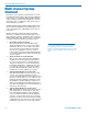
Remove the front panel hole caps.
Locking tabs on
opposite sides
The hole caps have locking tabs to
retain the cap when installed.
Use a flat blade screwdriver and
depress the locking tabs on one side
of the hole cap while pushing outward
on the cap. The cap will move outward
slightly to release the tabs on one side
of the plug.
Press down on the tabs with a flat blade screwdriver
while pushing outward on the cap with thumb or
finger to release one side
With one side of the cap released, use the handle of
the screwdriver to press firmly on the back of the cap
to remove it from the front panel.
Step 3
Remove the four screws holding the chassis cover,
then remove the cover by lifting the rear up.
CAUTION: The exposed components on the
circuit board are sensitive to static shock.
Wear an anti-static wrist strap grounded to
the housing of the receiver to avoid damaging
the components.
Step 4
Remove the nuts and washers from the upper two
BNC connectors and route the coaxial cables to the
front panel.