
User's Manual
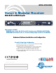


Venue 2 Wideband Receiver
LECTROSONICS, INC.
8
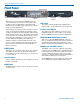
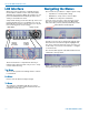
Removing Receiver Modules
1. Turn the power off.
2. Gently pull outwards on the side panel and push
the top of the clip sideways to release it from the
slot in the side panel.
3. Pull outward on the module to release the con-
nector and then lift it upward out of the chassis.
Holes in the underside of the chassis allow you to
grip the module on the top and bottom.
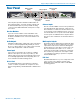
Rack Installation
1. Mount the receiver modules in the desired rack
location(s). There are no special ventilation re-
quirements.
2. Connect the antennas or coaxial cables to the an-
tenna upper input connectors on the rear panel.
Note: The frequency bandwidth of the antennas
must cover the range of the modules in use.
3. For multiple unit installations, a “loop thru” is avail-
able to feed two or three receivers from a single
antenna pair. Connect coaxial cables from the
multicoupler outputs on the first receiver to the
antenna inputs on the next receiver in the stack.
( )
( )
( )
( )
( )
( )
The upper connectors are the inputs connected
to the antennas on the first unit in the stack. The
lower connectors are the outputs that feed the
next assembly in the rack.
4. Plug the power supply into a suitable outlet and
plug the power connector into the Power Input
Jack.
5. Turn down the audio inputs on all the externally
connected equipment, then connect cables to the
appropriate Audio Output XLR Jacks.
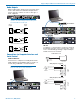
Hardware Installation
Receiver Modules
All modules must be within the frequency passband of
the host assembly. Frequency bands are marked on
the receiver modules.
When a module is set for Smart Diversity (antenna
phase switching), receiver modules can be installed in
any position in the mainframe chassis.
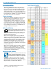
For ratio diversity operation, the module pair must be
on the same frequency band and positioned adjacent
to one another in the assembly as shown in the dia-
gram on top of the mainframe chassis. This will enable
Opti-Blend
TM
panning to mix the audio from the two
modules.
TM
Ratio Diversity Opti-Blend
TM
Channel Pairing
LINK
LINK
4
5
6
3
2
1
LINK
Installing Receiver Modules
Turn the power off.
The receiver modules interface with the main assem-
bly through multi-pin connectors on either side of the
chassis. Insert the module straight down and then slide
it toward the main housing to insert the connector pins.
The module should sit flush against the side of the
housing.
Caution: Make sure the connectors align correctly. Do
not force the module onto the tab. Excessive force may
damage the connectors.
Align the ridge on the retaining clip with the slot in the
chassis and press the clip downward until the ridge
snaps into the slot in the side panel.