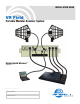
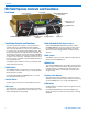
INSTALLATION GUIDE VR Field Portable Modular Receiver System Digital Hybrid Wireless™ (Patent Pending) Fill in for your records: Serial Number: Purchase Date: Rio Rancho, NM, USA www.lectrosonics.
VR Field Table of Contents Introduction..............................................................................................................................................................................................5 Unpacking the unit ................................................................................................................................................................................5 VR.Field.System.Controls.and.Functions.............................................
Digital Hybrid Wireless™ Modular Receiver System Installing the LecNet2™ USB Driver.................................................................................................................................................16 USB Driver Installation (Windows XP) - First Time .........................................................................................................................16 USB Driver Installation (Windows XP) - Subsequent Installations ..........................................
VR Field LECTROSONICS, INC.
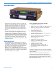
Digital Hybrid Wireless™ Modular Receiver System Introduction The purpose of this guide is to assist in the setup and operation of the VR Field System. This guide assumes familiarity with the VR Field System, its components and software menus and setup screens. To get the most out of the VR Field System, it is suggested that you review the information presented in the Reference Manual.
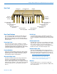
VR Field VR Field System Controls and Functions Front Panel LCD.Screen Function.Button PUSH.FOR.MENU/SELECT. Rotary.Control LEVEL.Control.for. PHONES.jack PHONES.Jack POWER.Button BACK.Button Receiver.Select. Buttons Front Panel Controls and Functions The VR Field System consists of a chassis (host as sembly) and one to six individual receiver modules. The front panel provides an easy-to-use LCD interface for system setup, monitoring and troubleshooting.
Digital Hybrid Wireless™ Modular Receiver System Rear Panel RS-232.Port Power.Input.Jack USB.Port Receiver. Modules.4-6 (Inside) Receiver. Modules.1-3 (Inside) XLR.Audio.Output..Jack. (Receiver.6) XLR.Audio.Output.Jack. (Receiver.1) XLR.Audio.Output.Jack. (Receiver.5) XLR.Audio.Output.Jack. (Receiver.4) XLR.Audio.Output.Jack. (Receiver.2) Antenna.(A).Input Antenna.(A).
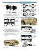
VR Field Hardware Installation Bottom View of the Chassis VRF.Front.Panel Installing/Removing Receiver Modules Up to six Receiver Modules can be installed in a VRF chassis. These modules may be installed at the factory or added later. Although the VR Field System is quite flexible, any com bination of Receiver Modules installed must be within the frequency block range of the VRF chassis. The frequency block range of the VRF chassis is displayed during the PowerUp Sequence. VRF.Rear.
Digital Hybrid Wireless™ Modular Receiver System Audio Output Wiring Diagrams Typical.Lectrosonics Antenna.Combinations ALP.Series RA500 SNA600 4. Insert a charged battery into the front panel, or plug the VR Field power supply into a suitable outlet and plug the power connector into the Power Input Jack (unscrew the power connector that goes to the battery). Repeat for each VR Field System being Typical USB Hookup for Single VR Field System Coaxial. Patch.Cables. (Not.Supplied) Antenna.
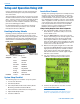
VR Field Setup and Operation Using LCD Use the following procedures to setup and operate the VR Field System using the front panel LCD, pushbut tons and controls. These procedures assume there is at least one receiver module installed and that receiver module is installed in Slot 1. If there is at least one receiver module installed, but it is not in Slot 1, then use the lowest numbered slot where a receiver module is installed as the starting point for the following procedures.
Digital Hybrid Wireless™ Modular Receiver System Using Scan to Find Clear Frequencies In crowded RF environments, it may not be possible to find enough clear channels using a Tuning Group. The internal spectrum scanner can be used to find clear channels. The Scan Function automatically selects two receivers (on from each frequency block) for spectrum scanning purposes. 1. Ensure all associated transmitters are turned off and all receivers are set to NORMAL tuning mode. 2.
VR Field OptiBlend (Ratio Diversity) Setup 1. From the Overview Screen, Navigate to SetupRx and then to the DivMode Setup Screen. 2. Press the front panel Receiver Select Button for either Receiver Module in the pair to be used for OptiBlend diversity. (In the example, Receiver Se lect button 5 or 6 was pressed.) Compat (compatibility) Mode This procedure assumes that the external equipment has already been connected to the appropriate XLR Audio Output Jacks on the rear panel.
Digital Hybrid Wireless™ Modular Receiver System Setting Audio Output Levels This sets the audio output level at the Audio Output XLR Jacks. The front panel LEVEL control is only for setting the audio output level in the PHONES jack. Note: In OptiBlend (ratio diversity) and Frequency Diversity modes, the Receiver Modules are paired (1-2, 3-4, 5-6). Setting the audio level output on one of the receivers in the pair, sets the audio output to the same level on its compliment. 1.
VR Field Setting Noise Reduction Mode 1. Access the SmartNR Setup Screen. 2. Select Receiver Module 1. 4. Repeat Step 3 until all transmitters are turned on and good signal strength is verified at each of the associated receiver modules, or receiver module pairs. Selected.Receiver Receiver.Module.Boxes 3.. Turn on the transmitter one at a time and observe the RF Signal strength meter for the associated receiver module in the Overview Screen. SmartNR.
Digital Hybrid Wireless™ Modular Receiver System 1. Verify that the compatibility modes of the receiver modules match the associated transmitters and that the transmitters are of the same type and model. 2. Setup the transmitters according to the manufactur er’s recommendations. 3. Navigate to the DivMode Setup Screen. 4. Plug a set of headphones into the front panel PHONES jack to monitor the blended output.
VR Field Installing LecNet2™ Software and USB Driver Part of the LecNet2™ software package is the VRpanel for the VR Field Receiver. This Graphical User Interface (GUI) is designed to allow easy setup and monitoring of the VR Field Receiver using a computer system running the Windows® 2000 or XP operating system. 1.. Place the LecNet2™ Installation Disk in the PC’s CD-ROM drive. Installing LecNet2™ Software 1. Remove any previously installed versions of Lec Net2™ software.
Digital Hybrid Wireless™ Modular Receiver System 4.. Windows will search the CD for the driver and when it has found it. If a dialog box opens warning you that the driver has not passed Windows Logo Test ing, click “Continue.Anyway”. 2.. Windows will discover the previously installed driver. If a dialog box opens warning you that the driver has not passed Windows Logo Testing, click “Continue.Anyway”. 5.. When the driver installation is complete, the final page of the Wizard appears. Click “Finish”.
VR Field USB Driver Installation (Windows 2000) Subsequent Installations 3.. Check only CD-ROM.drives then click “Next>” to search the LecNet2™ CD for the USB driver. Once the LecNet2™ USB driver is installed in a Win dows® 2000 system device, and subsequent LectNet2 USB devices will invoke the Found.New.Hardware. Wizard which will automatically load the LecNet2™ USB driver for the new device. 4. When the driver is found, the LecNet2™ device name will be displayed along with the location of the driver.
Digital Hybrid Wireless™ Modular Receiver System Setting Up the VR Field System Via USB Port Once the LecNet2™ software and USB drivers have been installed (see Installing LecNet2™ Software and USB Driver), setting up the VR Field System using a Windows® 2000 or XP computer system is possible. The following procedure is designed to assist new users to access the VRpanel and provide a basic understand of the layout.
VR Field Help Menu Help provides access to the online Help file, VRpanel demonstration mode and an About Box featuring the VRpanel’s current version number. Set Up VR The Set Up VR dialog is used to control all the stored settings for the currently selected VR system. The Help file offers users detailed information on the setup and operation of the VR Field System. Client Area The Client Area holds one or more panes, each graphi cally representing one VR system.
Digital Hybrid Wireless™ Modular Receiver System Receivers.1&2.in.Ratio.Diversity.Mode,.Rest.in. Switched.Diversity.Mode Factory Defaults Clicking this menu item restores the selected VR Field System to the factory default settings. The Factory Default Settings are: SetUpRx. Cursor.Select Receiver.Module. Frequency.Locations. Clicking Stop suspends the scan. Clicking Run re sumes the scan. Clicking Clear stops the scan and clears the spectrum data.
VR Field Frequency Coordination Intermodulation interference is a problem constantly lurking in the background, especially when working in environments where simultaneous productions are taking place in close proximity. In these cases, proper frequency coordination is a must. There are basically three methods to coordinate frequencies: • Use the built-in frequency groups • Scan for clear channels (See SmartTune™ and Scan Function.
Digital Hybrid Wireless™ Modular Receiver System Frequency Compatibility Diagram (See guidelines on page 16 for explanation) Rio Rancho, NM
VR Field The following guidelines should be observed when selecting compatible frequencies: 1.. Set.1.and.Set.2.are.NOT.compatible. Proper coordination requires that all frequencies be taken from either Set 1 or Set 2, but not a combina tion of the two. (The remaining guidelines make the assumption that you are choosing frequencies within one frequency set.) 2.. Frequencies.within.an.individual.frequency. block.in.the.same.Set.are.compatible..
Digital Hybrid Wireless™ Modular Receiver System Antenna Use and Placement The VR Field System is designed for rack mounting. Although it can be operated with two whip antennas, it is best to use remote antennas such as the SNA600 or ALP700 for optimum reception. Position the remote antennas at least three or four feet apart and not within three or four feet of large metal surfaces. If this is not possible, try to position the antennas so that they are as far away from the metal surface as is practical.
VR Field Service and Repair If your system malfunctions, you should attempt to correct or isolate the trouble before concluding that the equipment needs repair. Make sure you have followed the setup procedure and operating instructions. Check the interconnect ing cables and then go through the Troubleshooting section in this manual. We strongly recommend that you do.not try to repair the equipment yourself and do.not have the local repair shop attempt anything other than the simplest repair.
Digital Hybrid Wireless™ Modular Receiver System Rio Rancho, NM
LIMITED ONE YEAR WARRANTY The equipment is warranted for one year from date of purchase against defects in materials or workmanship provided it was purchased from an authorized dealer. This warranty does not cover equipment which has been abused or damaged by careless handling or shipping. This warranty does not apply to used or demonstrator equipment. Should any defect develop, Lectrosonics, Inc. will, at our option, repair or replace any defective parts without charge for either parts or labor.