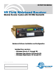
INSTRUCTION MANUAL VR Field Wideband Receiver Modular Receiver System with 230 MHz Bandwidth Hardware/Software Installation and Configuration Includes three versions: • Wideband (blocks 21 through 29) • Wideband Low (blocks 470 through 26) • Wideband High (blocks 25 through 29) Fill in for your records: Serial Number: Purchase Date: Rio Rancho, NM, USA www.lectrosonics.
VR Field Wideband Receiver 2 LECTROSONICS, INC.
Digital Hybrid Wireless™ Modular Receiver System Table of Contents Introduction..............................................................................................................................................................................................5 Unpacking the unit.................................................................................................................................................................................5 Controls and Functions.....................
VR Field Wideband Receiver NOTE: This equipment has been tested and found to comply with the limits for a Class B digital device, pursuant to Part 15 of the FCC Rules. These limits are designed to provide reasonable protection against harmful interference in a residential installation. The equipment generates, uses and can radiate radio frequency energy and, if not installed and used in accordance with the instructions, may cause harmful interference to radio communications.
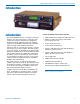
Digital Hybrid Wireless™ Modular Receiver System Introduction Introduction The Venue Wideband receiver is a modular rack mount design for use with a wide variety of transmitters from Lectrosonics and other manufacturers. Designed for maximum versatility and performance, the wideband design offers the flexibility needed in today’s changing and increasingly congested RF environments. A Venue receiver is a “system” that consists of a master unit and up to six receiver modules.
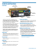
VR Field Wideband Receiver Controls and Functions Front Panel Function Button (labeled by the LCD) PUSH FOR MENU/SELECT Rotary Control Headphone LEVEL Control PHONES Jack POWER Switch BACK Button Receiver Select Buttons Battery Compartment The Venue receiver master unit (VRM) serves as a “host assembly” for up to six receiver modules. The standard module (VRS) and tracking module (VRT) can be mixed and matched in the assembly in any combination to suit the needs of various applications.
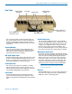
Digital Hybrid Wireless™ Modular Receiver System Rear Panel Balanced Audio Outputs 4-6 Power Input Antenna Inputs Balanced Audio Outputs 1-3 Receiver Modules 1-3 Receiver Modules 4-6 (under lower cover) RS-232 Port Multicoupler Outputs The rear panel provides six balanced XLR audio outputs, antenna inputs, “loop thru” antenna outputs from an internal multicoupler, a power jack with a locking connector, plus USB and RS-232 serial ports for setup and control.
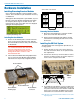
VR Field Wideband Receiver Hardware Installation Installing/Removing Receiver Modules Bottom View of the Chassis VRF Front Panel Up to six Receiver Modules can be installed in a VRF chassis. These modules may be installed at the factory or added later. Although the VR Field System is quite flexible, any combination of Receiver Modules installed must be within the frequency block range of the VRF chassis. The frequency block range of the VRF chassis is displayed during the PowerUp Sequence.
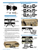
Digital Hybrid Wireless™ Modular Receiver System Audio Output Wiring Diagrams Typical Lectrosonics Antenna Combinations ALP Series A500RA SNA600 NOTE: Frequencies of the receiver modules must be within the range of whip antennas and the SNA600 dipole. The ALP Series antennas are wideband designs that cover the entire range. Typical USB Hookup for Single VR Field System Coaxial Patch Cables (Not Supplied) Antenna Inputs RS-232 Port 4.
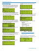
VR Field Wideband Receiver Initial Startup The display then switches to the overview of all six channels. When the Venue receiver is first powered up the LCD will show the firmware revision and the tuning range of the host assembly. The wideband version of the VRM covers the entire 230 MHz bandwidth of frequency blocks 21 through 29. Any slot that is not occupied by a module will leave a blank space in the overview display.
Digital Hybrid Wireless™ Modular Receiver System Navigating the LCD Menus and Screens Front panel controls provide access to screens and menus for setup. The Function Button, Back Button, Receiver Select buttons and the MENU/SELECT control are used to make selections and adjust parameters. In a setup screen such as the LockSet example shown here, up/down arrows prompt you to change the setting by rotating the MENU/SELECT control.
VR Field Wideband Receiver Resetting to Factory Defaults Resetting to Factory Defaults can be a time saver for setting up the system. Start with the power turned off, then hold Receiver Select Buttons 5 and 6 while powering up the system. Six compatibility modes are available to match various transmitter types. In this example, the Digital Hybrid compatibility mode is selected for receiver module 1. Press the Receiver Select button for each module and rotate the MENU/SELECT control to select the mode.
Digital Hybrid Wireless™ Modular Receiver System In this mode the signals from both antennas are combined into a single receiver module, with the phase of one of them inverted back and forth so that they always add to one another. The process reduces dropouts and provides a stronger signal than a single antenna. Select the receiver module with Receiver Select Button and rotate the MENU/SELECT control to the desired mode.
VR Field Wideband Receiver Note: In Frequency Diversity mode, both transmitters must be the same type (usually the same model). The microphones must also be placed very close together to minimize comb filtering. To prepare for operation in the Frequency Diversity mode, make the following adjustments: NORMAL MODE is the standard Lectrosonics mode with 256 frequencies in 100 kHz steps. A unique pilot tone is present for each frequency. 1. Set up the transmitters according to their instructions.
Digital Hybrid Wireless™ Modular Receiver System Finding Clear Frequencies with SmartTune SmartTune simplifies setup by scanning the tuning range of the receiver and automatically setting a receiver module to a clear frequency. A receiver module is selected, a scan is completed and the frequency is set for that module. A prompt appears, reminding you to turn on a transmitter on the newly selected frequency, and the procedure continues until all modules have been tuned to clear frequencies.
VR Field Wideband Receiver NOTE: In Ratio Diversity and Frequency Diversity modes, the receiver modules are paired 1-2, 3-4, 5-6. Setting the audio level output on either module in the pair, sets the audio output to the same level on both of them. Select the receiver module to use for scanning and press MENU/SELECT. The scanning begins automatically. 1. Navigate to the Level setup screen. 3.
Digital Hybrid Wireless™ Modular Receiver System Selecting Audio Phase Microphone wiring and other vagaries can alter the phase of an audio signal. To compensate for this, the phase of the audio output of each receiver module can be inverted. 1. Navigate to the Phase setup screen. 2. Select each receiver module with the Receiver Select Button and adjust the phase with the MENU/SELECT control. 2.
VR Field Wideband Receiver Battery status is displayed on the receiver detail screen, the overview screen and the info screen. Battery Gauges The display changes to a numerical readout when a timer mode is selected. Locking Out the Front Panel Controls Navigate to the LockSet setup screen. Rotate the MENU/SELECT control to the LOCKED or NOT LOCKED setting and press the control. When LOCKED is selected, no changes can be made to the configuration with the front panel controls.
Digital Hybrid Wireless™ Modular Receiver System Installing USB Drivers This sequence and the screens are typical of installing the drivers on a computer running 64-bit Windows 7. Insert the disk into your local drive. When the first screen appears, select Install USB Drivers for either the 32-bit or 64-bit version to match your computer operating system. The driver only needs to be installed one time on each computer that will be connected to the processors.
VR Field Wideband Receiver Installing LecNet2 Software on the button labeled I Agree, then on Next to continue with the installation. IMPORTANT: Install the USB driver BEFORE installing the software to simplify the process. See the steps on the previous page. This sequence and the screens are typical of installing the drivers on a computer running 64-bit Windows 7. Insert the disk and when the main screen appears, select Install LecNet2 Software.
Digital Hybrid Wireless™ Modular Receiver System When the confirmation screen appears, click on Next to continue with the installation. The installation takes place quickly, followed by the final screen that verifies that the software was installed correctly. Click on Close to exit the installer.
VR Field Wideband Receiver Setting Up the Venue Receiver Using VRpanel Once the LecNet2™ software and USB drivers have been installed, the Venue receiver can be configured with a software interface and a computer using a Windows® 2000, XP or VistaTM operating system. VRpanel is an intuitive software package that simplifies the setup and operation of the Venue receiver. This section of this manual is limited to the basic setup and configuration.
Digital Hybrid Wireless™ Modular Receiver System Main Window Top Menu Items The Main Window is organized in a straightforward manner with three pull down menus. Brief descriptions of these menus are presented here as an introduction. Full descriptions and instructions for the menu items are presented in the online Help. With multiple Venue receivers, a pane opens for each receiver, with positions for up to six receiver modules in each.
VR Field Wideband Receiver Scanning continues until it is suspended by the user. Click Stop to suspend the scanning. While scanning is suspended, select a receiver module with its radio button in the upper left of the dialog box. The cursor for the selected module will be highlighted, and can then be moved by left clicking and dragging the mouse. Click Run to resume the scan. Click Clear to stop the scan and clear the spectrum data.
Digital Hybrid Wireless™ Modular Receiver System Antenna Use and Placement The Venue System is designed for rack mounting. Although it can be operated with two whip antennas, it is best to use remote antennas such as the SNA600 or ALP Series for optimum reception. Position the remote antennas at least three or four feet apart and not within three or four feet of large metal surfaces. If this is not possible, try to position the antennas so that they are as far away from the metal surface as is practical.
VR Field Wideband Receiver Pre-coordinated Frequencies Groupings of compatible frequencies have been created to minimize intermodulation problems in multiple channel wireless systems. The frequencies can be used with Digital Hybrid and analog Lectrosonics wireless equipment. Compatibility with other brands is likely, but not guaranteed by Lectrosonics. The table provides two different sets of pre-coordinated frequencies for frequency blocks 470 through 29.
Digital Hybrid Wireless™ Modular Receiver System Compatibility Diagram BLOCK 24 Compatibility follows the pattern illustrated in the diagram at right. Grp a and Grp b contain the 16 frequencies shown in the table below (upper orange/white set). Grp c and Grp d contain the 16 frequencies shown in the table below (lower blue/white set). NOTE: There is no assurance that frequencies are compatible between the upper orange/white set and the lower blue/white set.
VR Field Wideband Receiver Diagnostics Multi-channel System Checkout Interference can result from a wide variety of sources including TV station signals, other wireless equipment in use nearby, or from intermodulation within a multichannel wireless system itself. Regardless of how the frequencies were coordinated, a final checkout procedure is always a good idea.
Digital Hybrid Wireless™ Modular Receiver System Accessories and Common Replacement Parts Remote Antennas ALP Series LPDA (log periodic dipole array) models ALP500 ALP620 SNA600 folding dipole antenna ALP650/L ALP Kit mounting hardware Coaxial Cable ARG2 coaxial cable - 2 ft. length ARG15 coaxial cable - 15 ft. length ARG25 coaxial cable - 25 ft. length ARG50 coaxial cable - 50 ft. length ARG100 coaxial cable - 100 ft.
VR Field Wideband Receiver Service and Repair If your system malfunctions, you should attempt to correct or isolate the trouble before concluding that the equipment needs repair. Make sure you have followed the setup procedure and operating instructions. Check the interconnecting cables and then go through the TROUBLESHOOTING section in this manual.
Digital Hybrid Wireless™ Modular Receiver System Rio Rancho, NM, USA 31
LIMITED ONE YEAR WARRANTY The equipment is warranted for one year from date of purchase against defects in materials or workmanship provided it was purchased from an authorized dealer. This warranty does not cover equipment which has been abused or damaged by careless handling or shipping. This warranty does not apply to used or demonstrator equipment. Should any defect develop, Lectrosonics, Inc. will, at our option, repair or replace any defective parts without charge for either parts or labor.