INSTALLATION GUIDE Venue Wideband Receiver Modular Receiver/Multicoupler System Hardware/Software Installation and Configuration Includes three models: • Wideband (blocks 21 through 29) • Wideband Low (blocks 470 through 26) • Wideband High (blocks 25 through 33) Fill in for your records: Serial Number: Purchase Date: Rio Rancho, NM, USA www.lectrosonics.
Venue Wideband Receiver 2 LECTROSONICS, INC.
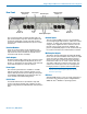
Digital Hybrid Wireless™ Modular Receiver System Introduction The Venue Wideband receiver is a modular rack mount design for use with a wide variety of transmitters from Lectrosonics and other manufacturers. Designed for maximum versatility and performance, the wideband design offers the flexibility needed in today’s changing and increasingly congested RF environments. A Venue receiver is a “system” that consists of a master unit and up to six receiver modules.
Venue Wideband Receiver 4 LECTROSONICS, INC.
Digital Hybrid Wireless™ Modular Receiver System Table of Contents Introduction............................................................................. 3 Venue System Controls and Functions................................ 6 Front Panel............................................................................ 6 Rear Panel............................................................................ 7 Hardware Installation............................................................. 8 Receiver Modules..
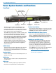
Venue Wideband Receiver Venue System Controls and Functions Front Panel Function Button (labeled by the LCD) Headphone LEVEL Control POWER Button BACK Button Receiver Select Buttons PUSH FOR MENU/SELECT Rotary Control PHONES Jack The Venue receiver master unit (VRM) serves as a “host assembly” for up to six receiver modules. The standard module (VRS) and tracking module (VRT) can be mixed and matched in the assembly in any combination to suit the needs of various applications.
Digital Hybrid Wireless™ Modular Receiver System Rear Panel Balanced Audio Outputs 4-6 Receiver Modules 4-6 Power Input RS-232 Port USB Port Multicoupler Outputs The rear panel provides six balanced XLR audio outputs, antenna inputs, “loop thru” antenna outputs from an internal multicoupler, a power jack with a locking connector, plus USB and RS-232 serial ports for setup and control. Receiver Modules Up to six receiver modules can be installed in each Venue receiver rack mount chassis.
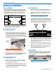
Venue Wideband Receiver Hardware Installation Receiver Modules Rack Installation VRS and VRT receiver modules can be mixed in the same chassis, For ratio diversity operation, both modules in the pair must be on the same frequency block and positioned in the assembly in keeping with the OPTI-BLEND labeling on top of the chassis housing. Front panel 1. Mount the receiver(s) in the desired rack location(s). There are no special ventilation requirements. 2.
Digital Hybrid Wireless™ Modular Receiver System Connections for Computer Interface The audio output wiring is as follows: Venue Output (+) (-) Connection to a computer can be made via USB or RS-232 ports. Multiple units are easily connected using a USB hub. Audio Input 2 3 1 (+) (-) SHIELD NOTE: Audio is not passed through these ports. They are used only for control and monitoring. SHIELD A single receiver connects directly to the computer.
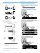
Venue Wideband Receiver Initial Startup The display then switches to the overview of all six channels. When the Venue receiver is first powered up the LCD will show the firmware revision and the tuning range of the host assembly. Any slot that is not occupied by a module will leave a blank space in the overview display. As the boot sequence continues, the display will switch to an overview of all six receiver channels. In this example, six receiver modules are installed but no transmitters are turned on.
Digital Hybrid Wireless™ Modular Receiver System Navigating the LCD Menus and Screens Front panel controls provide access to screens and menus for setup. The Function Button, Back Button, Receiver Select buttons and the MENU/SELECT control are used to make selections and adjust parameters. In a setup screen such as the LockSet example shown here, up/down arrows prompt you to change the setting by rotating the MENU/SELECT control.
Venue Wideband Receiver Resetting to Factory Defaults Resetting to Factory Defaults can be a time saver for setting up the system. Start with the power turned off, then hold Receiver Select Buttons 5 and 6 while powering up the system. Six compatibility modes are available to match various transmitter types. In this example, the Digital Hybrid compatibility mode is selected for receiver module 1. Press the Receiver Select button for each module and rotate the MENU/SELECT control to select the mode.
Digital Hybrid Wireless™ Modular Receiver System In order for TalkBack functionality to work on the Venue receiver, there needs to be at least one empty slot (and thus associated unused XLR) in the mainframe. The Venue’s microcontroller will automatically determine the next empty slot for any receiver set to TalkBack mode, and this empty slot will serve as the TalkBack output channel.
Venue Wideband Receiver When any Compat Mode other than Dig. Hybrid is selected, FIXED will automatically be selected. In this example, receiver modules 4, 5 and 6 are set to the FIXED mode with no adjustment available. Selecting Diversity Modes Navigate to the DivMode setup screen. of the RF signal levels in the modules begins when the RF level is still high, so the circuit can blend in more audio from the module with the stronger signal before the signal decays enough to cause noise.
Digital Hybrid Wireless™ Modular Receiver System CUSTOM MODE is a special mode used to store up to 50 frequencies per block in 25 kHz steps. Frequencies are stored in memory in a “table” with positions numbered 0 through 49. The pilot tone frequency is defined by the position of each frequency in the table. NOTE: Custom Mode would require programming from a factory authorized service center for proper operation The Receiver Detail window will indicate the selected mode and frequency information.
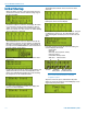
Venue Wideband Receiver 1. Navigate to the Tuning setup screen. Cursor blinks Function Button Clear Spectrum Strong Interference 5. Press the BACK button to return to the “Stop Mode.” 2. Select each module in turn with the Receiver Select Buttons and select the desired tuning group. Then return to the overview screen. 3. Turn transmitters off.
Digital Hybrid Wireless™ Modular Receiver System 2. Select each receiver one at a time with the buttons under the LCD and rotate the knob to adjust the output to the desired level. Function Button Selected Receiver Output Level Tone On/Off Indicator (Shown in Off position.) 3. Use the Tone Generator to adjust other equipment to match the output level from the receiver with full modulation of the transmitter. Press the Function Button to start the tone.
Venue Wideband Receiver but monitor its status with the battery timer in the main window. AA ALK Transmitter uses a AA alkaline battery. Monitor voltage with battery icon in main window. AA LTH Transmitter uses a AA lithium battery. Monitor voltage with battery icon in main window. AA TIM Battery Gauges Transmitter uses an AA battery. Display its voltage normally in the battery level window but monitor its status with the battery timer in the main window.
Digital Hybrid Wireless™ Modular Receiver System Installing LecNet2™ Software and USB Driver LecNet2 software includes VRpanel for easy setup and monitoring of the Venue Receiver using a computer system running Windows® 2000, XP or VistaTM operating systems. 2. On the first page of the Wizard, select Install from a list or specific location (Advanced) and click “Next>” to continue. Installing LecNet2™ Software 1.
Venue Wideband Receiver 5. When the driver installation is complete, the final page of the Wizard appears. Click “Finish” to close the Found New Hardware Wizard. USB Driver Installation (Windows XP) Subsequent Installations 3. When the driver installation is complete, the final page of the Wizard appears. Click “Finish” to close the Found New Hardware Wizard. The Windows XP operating system regards all LecNet2™ devices as separate USB devices because each has a unique serial number.
Digital Hybrid Wireless™ Modular Receiver System 2. Select Search for a suitable driver for my device (recommended) and click “Next >” to continue. USB Driver Installation (Windows 2000) Subsequent Installations Once the LecNet2™ USB driver is installed in a Windows® 2000 system device, subsequent LectNet2 USB devices will invoke the Found New Hardware Wizard which will automatically load the LecNet2™ USB driver for the new device. Firmware Update Instructions 3.
Venue Wideband Receiver Setting Up the Venue Receiver Using VRpanel Once the LecNet2™ software and USB drivers have been installed, the Venue receiver can be configured with a software interface and a computer using a Windows® 2000, XP or VistaTM operating system. VRpanel is an intuitive software package that simplifies the setup and operation of the Venue receiver. This section of this manual is limited to the basic setup and configuration.
Digital Hybrid Wireless™ Modular Receiver System Main Window Top Menu Items The Main Window is organized in a straightforward manner with three pull down menus. Brief descriptions of these menus are presented here as an introduction. Full descriptions and instructions for the menu items are presented in the online Help. With multiple Venue receivers, a pane opens for each receiver, with positions for up to six receiver modules in each.
Venue Wideband Receiver Scanning continues until it is suspended by the user. Click Stop to suspend the scanning. While scanning is suspended, select a receiver module with its radio button in the upper left of the dialog box. The cursor for the selected module will be highlighted, and can then be moved by left clicking and dragging the mouse. Click Run to resume the scan. Click Clear to stop the scan and clear the spectrum data.
Digital Hybrid Wireless™ Modular Receiver System Antenna Use and Placement The Venue System is designed for rack mounting. Although it can be operated with two whip antennas, it is best to use remote antennas such as the SNA600 or ALP Series for optimum reception. Position the remote antennas at least three or four feet apart and not within three or four feet of large metal surfaces. If this is not possible, try to position the antennas so that they are as far away from the metal surface as is practical.
Venue Wideband Receiver Pre-coordinated Frequencies Groupings of compatible frequencies have been created to minimize intermodulation problems in multiple channel wireless systems. The frequencies can be used with Digital Hybrid and analog Lectrosonics wireless equipment. Compatibility with other brands is likely, but not guaranteed by Lectrosonics. The table provides two different sets of pre-coordinated frequencies for frequency blocks 470 through 29.
Digital Hybrid Wireless™ Modular Receiver System Compatibility Diagram BLOCK 24 Compatibility follows the pattern illustrated in the diagram at right. Grp a and Grp b contain the 16 frequencies shown in the table below (upper orange/white set). Grp c and Grp d contain the 16 frequencies shown in the table below (lower blue/white set). NOTE: There is no assurance that frequencies are compatible between the upper orange/white set and the lower blue/white set.
Venue Wideband Receiver Diagnostics Multi-channel System Checkout Interference can result from a wide variety of sources including TV station signals, other wireless equipment in use nearby, or from intermodulation within a multichannel wireless system itself. Regardless of how the frequencies were coordinated, a final checkout procedure is always a good idea.
Digital Hybrid Wireless™ Modular Receiver System Accessories and Common Replacement Parts Remote Antennas ALP500 ALP Series LPDA (log periodic dipole array) models ALP620 SNA600 folding dipole antenna ALP650 ALP Kit mounting hardware Coaxial Cable ARG2 coaxial cable - 2 ft. length ARG15 coaxial cable - 15 ft. length ARG25 coaxial cable - 25 ft. length ARG50 coaxial cable - 50 ft. length ARG100 coaxial cable - 100 ft.
Venue Wideband Receiver Service and Repair If your system malfunctions, you should attempt to correct or isolate the trouble before concluding that the equipment needs repair. Make sure you have followed the setup procedure and operating instructions. Check the interconnecting cables and then go through the TROUBLESHOOTING section in this manual. We strongly recommend that you do not try to repair the equipment yourself and do not have the local repair shop attempt anything other than the simplest repair.
Digital Hybrid Wireless™ Modular Receiver System Rio Rancho, NM, USA 31
LIMITED ONE YEAR WARRANTY The equipment is warranted for one year from date of purchase against defects in materials or workmanship provided it was purchased from an authorized dealer. This warranty does not cover equipment which has been abused or damaged by careless handling or shipping. This warranty does not apply to used or demonstrator equipment. Should any defect develop, Lectrosonics, Inc. will, at our option, repair or replace any defective parts without charge for either parts or labor.