INSTALLATION GUIDE For firmware up to Ver. 3.9 Venue Receiver Modular Receiver System with 50 MHz Bandwidth Hardware/Software Installation and Configuration Fill in for your records: Serial Number: Purchase Date: Rio Rancho, NM, USA www.lectrosonics.
Venue 2 LECTROSONICS, INC.
Digital Hybrid Wireless™ Modular Receiver System Introduction The Venue Narrowband receiver host assembly is a modular rack mount, DSP-based wireless receiver for use with a wide variety of transmitters from Lectrosonics and other manufacturers. Versatility and perfor mance are at the core of the design, with configurations and options to address an increasingly congested RF environment. The narrowband filters used in the multicoupler provide additional suppression of RF energy on adjacent channels.
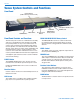
Venue Venue System Controls and Functions Front Panel Function Button (enables functions shown on LCD) Headphone LEVEL Control POWER Button BACK Button Receiver Select Buttons Front Panel Controls and Functions The Venue System consists of a VRM master assembly and one to six individual receiver modules. The VRM front panel provides an easy-to-use LCD interface for system setup, monitoring and troubleshooting.
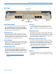
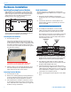
Digital Hybrid Wireless™ Modular Receiver System Rear Panel Antenna Inputs Receiver Modules 4-6 RS-232 Port USB Port Multicoupler Outputs Rear Panel Features The rear panel provides six balanced XLR audio out puts, two 50 Ohm BNC antenna inputs, two 50 Ohm BNC antenna outputs from an internal multicoupler, a power jack with a locking connector, with USB and RS 232 serial ports for setup and control.
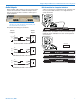
Venue Hardware Installation Installing/Removing Receiver Modules VRS and VRT receiver modules can be mixed in one VRM chassis, For ratio diversity operation, both mod ules in the pair must be on the same frequency block and positioned in the assembly in keeping with the labeling on top of the chassis housing. Front panel Rack Installation The Venue Receiver is designed for standard rack mount installation. Each VRM chassis occupies a single rack space. 1.
Digital Hybrid Wireless™ Modular Receiver System Audio Outputs USB Connection for Computer Interface Balanced XLR audio outputs on the rear panel can be used to drive balanced or unbalanced inputs at line level on any type of mixer, recorder or other type of audio equipment. A direct connection is made between the computer and the rear panel USB connector on a single Venue for setup and control.
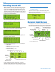
Venue Powering On and Off When the Venue receiver is first powered up the LCD will show the firmware revision and the tuning range of the host assembly. The narrowband version of the VRM covers a 50 MHz bandwidth, which includes two adjacent frequency blocks. The firmware in the narrow band version launches a boot sequence automatically to detect the installed modules. The receiver will automatically start the detection se quence to identify the modules installed.
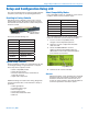
Digital Hybrid Wireless™ Modular Receiver System Setup and Configuration Using LCD The front panel knob, buttons and LCD enable complete complete system setup for all operating parameters. Resetting to Factory Defaults Resetting to Factory Defaults can be a time saver for setting up the system. Start with the power turned off, then hold Receiver Select buttons 5 and 6 while power ing up the system.
Venue Select Diversity Modes Frequency Diversity Press MENU/SELECT and rotate the knob to SetUpRx and press the knob. The SetUpRx screen provides menu selections for various operating parameters. Rotate the knob to DivMode and press the knob again.
Digital Hybrid Wireless™ Modular Receiver System Find Clear Channels Using Tuning Groups to Find Clear Channels Under the SetUpRx menu, Tuning modes can be se lected for manual frequency selection. There are four pre-coordinated frequency groups, plus two groups that can be customized for specific applica tions. Groups “a” though “d” are stored frequencies that are free from IM. Groups “u” and “v” are user defined to build custom groups. In the sequence that follows “Group a” is used as the example. 1.
Venue Adjust Audio Output Levels Setting Transmitter Battery Status Monitoring This sets the audio output level at the Audio Output XLR Jacks. The front panel LEVEL knob is only for adjusting the loudness at the PHONES jack. The key is to provide as high a level signal as possible without overdriving the input to external equipment or driving a subsequent stage in the signal chain into limit ing or compression.
Digital Hybrid Wireless™ Modular Receiver System Locking Out the Front Panel Controls From the overview screen press the knob to enter the Top Menu and select LockSet. Rotate the knob either direction to select LOCKED or UNLOCKED. When the settings are LOCKED no changes can be made to the configuration. If an attempt is made to change a setting, the LCD will flash a reminder that the settings are locked. Selecting the Noise Reduction Mode Two different DSP-based noise reduction modes are available: 1.
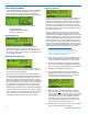
Venue Installing LecNet2™ Software and USB Driver Part of the LecNet2™ software package is the VRpanel for the Venue Receiver. This Graphical User Interface (GUI) is designed to allow easy setup and monitoring of the Venue Receiver using a computer system running the Windows® 2000, XP or VistaTM operating system. 2. On the first page of the Wizard, select Install from a list or specific location (Advanced) and click “Next>” to continue. Installing LecNet2™ Software 1.
Digital Hybrid Wireless™ Modular Receiver System 5. When the driver installation is complete, the final page of the Wizard appears. Click “Finish” to close the Found New Hardware Wizard. 2. Windows will discover the previously installed driver. If a dialog box opens warning you that the driver has not passed Windows Logo Testing, click “Continue Anyway.
Venue USB Driver Installation (Windows 2000) First Time Use the following procedure when LecNet2™ device is connected to the Windows 2000-based PC for the first time. 1. Connect a USB cable between the Venue Receiv er’s USB port and the USB power on the computer system. Place the LecNet2™ Installation Disk in the PC’s CD-ROM drive and click “Next>” to display the next page. 5. Click “Finish” when the installation is complete. 2.
Digital Hybrid Wireless™ Modular Receiver System Setting Up the VR System Via USB Port Once the LecNet2™ software and USB drivers have been installed, the Venue System can be configured with a software interface and a computer using a Win dows® 2000, XP or VistaTM operating system. The following procedure is designed to assist new users to access the VRpanel and provide a basic understand of the layout.
Venue Help Menu Help provides access to the online Help file, VRpanel demonstration mode and an About Box featuring the VRpanel’s current version number. Set Up VR The Set Up VR dialog is used to control all the stored settings for the currently selected VR system. The Help file offers users detailed information on the setup and operation of the Venue System. Client Area The Client Area holds one or more panes, each graphi cally representing one VR system.
Digital Hybrid Wireless™ Modular Receiver System Receivers 1&2 in Ratio Diversity Mode, Rest in Switched Diversity Mode Factory Defaults Clicking this menu item restores the selected Venue System to the factory default settings.
Venue 20 LECTROSONICS, INC.
Digital Hybrid Wireless™ Modular Receiver System Antenna Use and Placement The Venue System is designed for rack mounting. Although it can be operated with two whip antennas, it is best to use remote antennas such as the SNA600 or ALP700 for optimum reception. Position the remote antennas at least three or four feet apart and not within three or four feet of large metal surfaces. If this is not possible, try to position the antennas so that they are as far away from the metal surface as is practical.
Venue Pre-coordinated Frequencies Intermodulation interference is a problem constantly lurking in the background, especially when working in environments where simultaneous productions are taking place in close proximity. In these cases, proper frequency coordination is a must. There are basically three methods to coordinate frequencies: • Use the built-in frequency groups • Scan for clear channels (See SmartTune™ and Scan Function.
Digital Hybrid Wireless™ Modular Receiver System Frequency Compatibility Diagram (see next page for details) BLOCK 25 BLOCK 26 BLOCK 27 BLOCK 28 BLOCK 29 FREQ SW SET US TV CH FREQ SW SET US TV CH FREQ SW SET US TV CH FREQ SW SET US TV CH FREQ SW SET 640.500 0,5 tv42 666.100 0,5 tv46 691.700 0,5 tv50 717.300 0,5 tv55 742.900 0,5 US TV CH tv59 641.100 0,B tv42 666.700 0,B tv46 692.300 0,B tv51 717.900 0,B tv55 743.500 0,B tv59 642.000 1,4 tv42 667.
Venue Multi-channel System Checkout Interference can result from a wide variety of sources including TV station signals, other wireless equipment in use nearby, or from intermodulation within a multi channel wireless system itself. Regardless of how the frequencies were coordinated, a final checkout proce dure is always a good idea. IMPORTANT: Any time a frequency is changed on any of the systems in use, you must start at the beginning and go through this procedure again for all systems.
Digital Hybrid Wireless™ Modular Receiver System Accessories and Common Replacement Parts Remote Antennas ALP Series LPDA (log periodic dipole antenna) models SNA600 folding dipole antenna ALP500 ALP Kit mounting hardware ALP620 ALP650 Coaxial Cable ARG2 coaxial cable - 2 ft. length ARG15 coaxial cable - 15 ft. length ARG25 coaxial cable - 25 ft. length ARG50 coaxial cable - 50 ft. length ARG100 coaxial cable - 100 ft.
Venue Service and Repair If your system malfunctions, you should attempt to correct or isolate the trouble before concluding that the equipment needs repair. Make sure you have followed the setup procedure and operating instructions. Check the interconnecting cables and then go through the TROUBLESHOOTING section in this manual. We strongly recommend that you do not try to repair the equipment yourself and do not have the local repair shop at tempt anything other than the simplest repair.
Digital Hybrid Wireless™ Modular Receiver System Rio Rancho, NM 27
Venue LIMITED ONE YEAR WARRANTY The equipment is warranted for one year from date of purchase against defects in materials or workmanship provided it was purchased from an authorized dealer. This warranty does not cover equipment which has been abused or damaged by careless handling or shipping. This warranty does not apply to used or demonstrator equipment. Should any defect develop, Lectrosonics, Inc. will, at our option, repair or replace any defective parts without charge for either parts or labor.