UT700 ENCRYPTED DIGITAL UHF HANDHELD TRANSMITTER OPERATING INSTRUCTIONS and trouble-shooting guide LECTROSONICS, INC. Rio Rancho, NM www.lectrosonics.
UT700 TABLE OF CONTENTS INTRODUCTION ................................................................................................... 2 GENERAL TECHNICAL DESCRIPTION ............................................................. 3 CONTROLS AND FUNCTIONS ........................................................................... 6 VARIMIC CONTROLS ........................................................................................... 8 BATTERY INSTALLATION ............................................
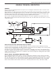
Digital Frequency Agile UHF Hand-held Transmitter GENERAL TECHNICAL DESCRIPTION GENERAL The 700 series encrypted digital wireless microphones use an all-digital communications link for excellent sound quality and data security. In the transmitter, the audio first passes through a DSP-controlled dual envelope analog limiter. The signal is then digitized and fed to a DSP (digital signal processor).
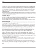
UT700 RF OUTPUT SECTION Intermodulation (IM) occurs in the final amplifier stages of conventional transmitters when the transmitters are within a few feet of each other. This can create serious problems in multichannel wireless systems when an IM signal falls on the carriers, IF frequencies, local oscillator and image frequencies of the systems being operated. To eliminate this problem in the UT700, the modulated radio signal passes through a circular isolator before entering the antenna.
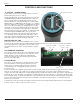
Digital Frequency Agile UHF Hand-held Transmitter MICROPHONE ELEMENT The UT400 includes the Lectrosonics VariMic mic element. The VariMic is a cardioid condenser back electret microphone that is adapted for the unique circumstances of wireless microphones. The problems it solves are dynamic range, handling noise and low frequency noise (rumble or wind).
UT700 CONTROLS AND FUNCTIONS “P” SWITCH – POWER ON/OFF A slide switch (located on the outside bottom of the unit) which turns battery power on and off. The Power LED glows green when the battery is good and the ON/OFF switch is ON. The lamp will glow red as the battery voltage drops and finally flashes when there is about 30 minutes of operation left with the recommended alkaline battery. A NiMh battery will give little or no warning when it is depleted.
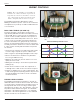
Digital Frequency Agile UHF Hand-held Transmitter HIDING THE POWER LED This unit has no provision for disabling the LEDs. The audio LEDs are covered during normal use but the power LED is exposed. If the light is objectionable, we recommend covering the LED with a piece of tape. FREQUENCY ADJUST 6 2 Two rotary switches (located under the battery door) adjust the center frequency of the carrier. The Coarse adjustment adjusts the frequency in 1.6 MHz steps and the fine in 100 kHz steps.
UT700 VARIMIC CONTROLS Caution - Due to the high RF levels surrounding the transmitter, the sound of the Varimic capsule may be temporarily affected if the metal windscreen is not in place. Always make the final decision about sound balance and quality with the windscreen in place. The VariMic head includes adjustments for Bass, Midrange and Treble response. There is also an attenuation adjustment to provide up to 15dB of additional headroom if needed.
Digital Frequency Agile UHF Hand-held Transmitter Note: The attenuator should not be used as a level control. The Audio Level control inside the battery compartment is the main level control. Adjust the attenuator only when the Audio Level control is turned completely down and more headroom is still needed. Be sure to set the attenuator back to its original setting for normal operation.
UT700 BATTERY INSTALLATION The transmitter is powered by a standard alkaline or lithium 9 Volt battery. It is important that you use ONLY an ALKALINE or LITHIUM battery for longest life. Standard zinc-carbon batteries marked “heavy-duty” or “longlasting” are not adequate. Ni-cad rechargeable batteries will only provide 1.5 hours of operation, or less, and will run down quite abruptly. Unless it is cold, alkaline batteries provide over 4.5 hours of operation.
Digital Frequency Agile UHF Hand-held Transmitter OPERATING INSTRUCTIONS ADJUSTING THE GAIN 1) Install a fresh battery. Leave the battery cover off for further adjustment. 2) On the bottom panel, move the “P” (power) switch to ON, toward the LED. Observe that the battery status LED is glowing green indicating a good battery. If the LED is glowing red, replace the battery. Note: If the security level is set to “2”, the receiver must be powered on before the transmitter.
UT700 TROUBLESHOOTING Before going through the following chart, be sure that you have a good battery in the transmitter. It is important that you follow these steps in the sequence listed. SYMPTOM POSSIBLE CAUSE TRANSMITTER BATTERY LED OFF 1) Battery is inserted backwards. 2) Battery is dead, or too low to be used. NO TRANSMITTER MOD LEVEL LEDs 1) Gain control turned all the way down. 2) Battery is in backwards. Check power LED. 3) Mic capsule is damaged or malfunctioning.
Digital Frequency Agile UHF Hand-held Transmitter MICROPHONE HAS A “WHINE” NOISE IN THE BACKGROUND WHICH VARIES AS THE MIC CABLE IS MOVED 1) Install bypass capacitors at both ends of the mic cable use the factory supplied microphone. RECEIVER OUTPUTS AN EXTREMELY LOUD, HISSY, SWISHY SOUND 1) Encryption keys in transmitter and receiver do not match. Refer to receiver manual to choose a new key and send it to the transmitter.
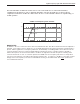
UT700 SPECIFICATIONS AND FEATURES Operating principle: Modulation type: Sample rate: Audio coder: Encryption key length: Bit rate: Operating frequencies: Frequency selection: RF Power output: Frequency stability: Equivalent input noise: Spurious radiation: Input Level: Input compressor: Gain control range: Modulation indicators: Low frequency roll-off adjustment: Controls: Proprietary digital modulation with encryption Modified pi/4 DQPSK 44.
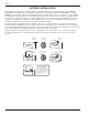
Digital Frequency Agile UHF Hand-held Transmitter SERVICE AND REPAIR If your system malfunctions, you should attempt to correct or isolate the trouble before concluding that the equipment needs repair. Make sure you have followed the setup procedure and operating instructions.
LIMITEDONE ONE YEAR WARRANTY LIMITED YEAR WARRANTY The equipment is warranted for one year from date of purchase against defects in materials or workmanship provided it was purchased from an authorized dealer. This warranty does not cover equipment which has been abused or damaged by careless handling or shipping. This warranty does not apply to used or demonstrator equipment. Should any defect develop, Lectrosonics, Inc.