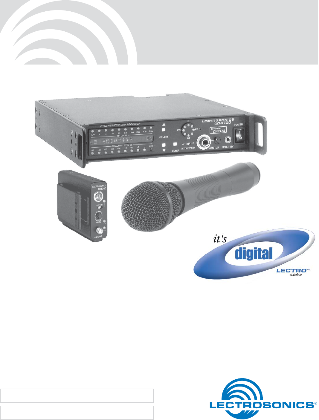
INSTRUCTION MANUAL 700 Series Encrypted Digital UHF Wireless System Includes: UDR700 UM700 UT700 Fill in for your records: Serial Number: Purchase Date: Rio Rancho, NM, USA www.lectrosonics.
UDR700 / UM700 / UT700 Table of Contents Introduction ............................................................................................................................................................................................ 5 Overall System Design ......................................................................................................................................................................... 5 UDR700 Block Diagram ...................................................
Encrypted Digital Wireless System UM700 Controls and Functions .......................................................................................................................................................... 14 Input Jack ........................................................................................................................................................................................... 14 Power On/Off Switch ....................................................................
UDR700 / UM700 / UT700 4 LECTROSONICS, INC.
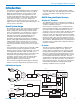
Encrypted Digital Wireless System Introduction The 700 Series encrypted digital wireless microphone system uses a digital audio chain and an encrypted digital RF communications link for excellent sound quality and data security. The applications for this system include high-end motion picture, studio and stage, and boardrooms, courtrooms and conference rooms where security is a concern.
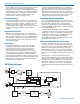
UDR700 / UM700 / UT700 The 244 MHz from the first IF is reduced to the second IF of 10.7 MHz, and is then fed to the Quadrature Detector. The first mixer is a GaAs MMIC device with a rated IP3 (third order intercept) of +24 dBm to minimize undesired IM products. Because the signal is digital, thermal drift in the detector has little effect on the signal’s content, unlike an analog receiver.
Encrypted Digital Wireless System Digital Signal Processing and Modulation Frequency Agility The preamplified and limited audio signal is converted to digital using a 24-bit A/D converter and fed to the DSP. Within the DSP, the audio is encoded to reduce the bit rate and increase entropy in the data stream prior to encryption. The data stream is then encrypted and apportioned into packets, delimited by packet headers.
UDR700 / UM700 / UT700 supplied with 48 Volts. A unique 16-position sensitivity control at the element itself can also adjust the sensitiv ity over a 15 dB range. This is in addition to the normal gain control in the wireless microphone. The result is the widest dynamic range of any condenser mic in a wireless microphone.
Encrypted Digital Wireless System The 700 Series Encryption System To guard against eavesdropping, the encryption in the 700 Series digital wireless system makes use of several processes and a unique key setup procedure to provide a high level of entropy and thus maximum security. A 128 bit key is used to create a formidable barrier against brute force attacks attempting to break the encryption code. The result is 340 trillion, trillion, trillion possible key combinations.
UDR700 / UM700 / UT700 10 LECTROSONICS, INC.
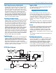
Encrypted Digital Wireless System UDR700 Controls and Functions UDR700 Front Panel Information and Status Display RF Level Indicator Audio Monitor Jack ROTA-VERSITY Switch RF Level Indicator A 10-segment LED strip indicates the level of the incoming RF signal. The strip is calibrated to provide accurate indications from 1 uV to 1 mV. The LEDs are highly visible from a distance. Note: A digital wireless receiver behaves differently than an analog receiver during weak RF signal conditions.
UDR700 / UM700 / UT700 UDR700 Rear Panel AC Power Input Connector EXT Power Connector AUDIO OUTPUT Jack PHASE Switch GND LIFT Digital Audio AES-3id Analog Audio Output Control AC Power Supply The UDR700 has a universal switching power supply which operates on AC voltages ranging from 95 to 240 Volts, 50 or 60 Hz. Since the power supply is self protected against line transients, short circuits, and over current conditions, there is no external fuse.
Encrypted Digital Wireless System To toggle between BUTTONS ENABLED and BUT TONS DISABLED, press and hold the SELECT Up button while setting the POWER switch to On. Menu Interface The menu interface consists of six linked menus: Group Tuning Menu The Group Tuning menu displays the current group (the three groups are designated A, B, and C) and the selected frequency within that group. The Transmitter Frequency Select Switch settings are shown at right, as on the other tuning menus.
UDR700 / UM700 / UT700 UM700 Controls and Functions Frequency Select Switches Left Panel LECTROSONICS UM700 Input Jack FREQUENCY 1.6MHz 100kHz Power LED E D C B A F 0 1 2 3 4 5 9 8 7 6 E D C B A F 0 1 2 3 4 5 9 8 7 6 OFF ON Power ON/OFF Switch Audio Level Control Belt Clip AUDIO LEVEL –10 Modulation LEDs –20 ANTENNA 75 Hz SMA Antenna Jack Font Panel 35 150 LF ROLL OFF FCCID:DBZUM700 Lectrosonics, Inc. Made in U.S.A.
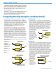
Encrypted Digital Wireless System The insulated flexible galvanized steel cable antenna supplied with the transmitter is cut to 1/4 wavelength of the center of the frequency block (the frequency range) of the transmitter. It is removable via an SMA connec tor. The SMA connector is a 50 Ohm RF port which can also be connected directly to test equipment.
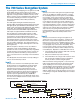
UDR700 / UM700 / UT700 UT700 Controls and Functions Encryption Key Link Power LED Audio Level Control Modulation LEDs -10 -20 Power On/Off Switch Fine Coarse Frequency Switches Battery Compartment Power On/Off Switch The Power On/Off slide switch is located on the outside bottom of the unit and controls power to the transmitter. Power LED The Power LED glows green when the battery is good and the On/Off switch is set to On.
Encrypted Digital Wireless System Modulation LEDs UT700 Battery Installation The Modulation LEDs (located under the Battery Compartment Door) provide a visual indication of the input audio signal level from the microphone. These two bicolor LEDs can glow either red or green to indicate modulation levels.
UDR700 / UM700 / UT700 18 LECTROSONICS, INC.
Encrypted Digital Wireless System System Installation and Operating Instructions System Setup 1) Locate a suitable operating location where the receiver will not be subjected to extreme tempera ture variations and possible bumps and drops. Try to route all wiring so it will not cross walkways or aisles. 2) Connect the power. For AC operation, connect the female end of the power cord to the AC input jack on the rear panel and plug the other end into a suitable electrical outlet.
UDR700 / UM700 / UT700 6) Set the front panel POWER switch to On and observe the POWER UP SEQUENCE. (See Information and Status Display Menus and Func tions. Warning: Do not turn on the associated transmitter(s). 9) Determine the security level required. (See The 700 Series Encryption System.) 10) Turn the UDR700 Off, then press and hold the SELECT Down button while turning the UDR700 back on. The display will show the current security level. The default is Level 1.
Encrypted Digital Wireless System Note: Each transmitter uses a different Encryption Cable. (See Encryption Key Cables.) 16) Press the SELECT Up button on the UDR700 to send the encryption key to the transmitter. Depend ing on the transmitter, the Power LED on the UT700 or the two Modulation LEDs on the UM700 blink to confirm receipt of the new key.
UDR700 / UM700 / UT700 Note: The -40 setting is approximately equal to 10 mV, the 0 position will give 0.775 VRMS, and the +15 setting will allow up to 4.4 VRMS when the transmitter is fully modulated. The correct setting will depend on the requirements of your sound or recording system. 22) If necessary, perform a walk test to map the effec tive operating range for the transmitter(s) prior to the beginning of the function.
Encrypted Digital Wireless System Protecting the Encryption Key The encryption key is never displayed, and once a key transfer session is complete, the existing key can never again be transferred out the receiver’s security port. However, the key is stored inside the transmitter and the receiver, so you should treat the equipment as you would a key, storing it in a safe place for as long as the key is important.
UDR700 / UM700 / UT700 5-Pin Input Jack Wiring (UM700) Preamp Level Control The wiring diagrams shown in Wiring Hookups For Different Sources represent the basic wiring configura tions necessary for the most common types of micro phones and other audio inputs. Some microphones may require extra jumpers or a slight variation in the diagrams shown. The VariMic™ head includes an attenuator to provide an additional 15 dB of headroom when needed.
Encrypted Digital Wireless System PIN 5 - 40 k high impedance, line level input for tape decks, mixer outputs, musical instruments, etc. Please specify the part number for the desired lead style.
UDR700 / UM700 / UT700 26 LECTROSONICS, INC.
Encrypted Digital Wireless System Troubleshooting This manual applies only to UDR700 version 3.0/3.0 and higher. Power Problems UDR700 Display not lit or dimly lit Power cord between main power supply and UDR700 disconnected or defective. External power supply disconnected, defective or inadequate. The External DC power input is protected by an auto-reset polyfuse.
UDR700 / UM700 / UT700 Audio Problems No audio output, audio leds blinking in sequence, LED display occasionally flashes "POWER TX OFF+ON" or "NEW KEY REQUIRED". Receiver indicates RF but no audio, and problem is not encryption key No sound (or low sound level), receiver indicates proper audio modulation Receiver outputs an extremely loud, hissy or swishy sound System is operating in security level 2 ("POWER TX OFF+ON") or 3 ("NEW KEY REQUIRED") and is not synchronized.
Encrypted Digital Wireless System Excessive feedback Microphone has a “whine” noise in the background which varies as the mic cable is moved. (UM700 specific) Transmitter gain (audio level) too high. Check gain adjustment and/or reduce receiver output level. Microphone too close to speaker system. Move microphone closer to the user’s mouth, and lower the sound system volume. The 700 Series modulation has an AM component which is more easily detected than FM by sensitive audio circuits.
UDR700 / UM700 / UT700 Specifications Overall System Latency: Operating principle: Modulation type: Sample rate: Audio coder: Encryption key length: Bit rate: Operating frequencies: (depending upon local regulations) Frequency selection: Frequency Adjustment Range: System Specifications Audio frequency response: Audio dynamic range: Audio Distortion: Controls: 2.5 ms Proprietary digital modulation with encryption Modified pi/4 DQPSK 44.
Encrypted Digital Wireless System Rio Rancho, NM 31
UDR700 / UM700 / UT700 Replacement Parts and Accessories Part No. Description A500RA Right angle, flexible whip UHF antenna A600 Log Periodic Dipole Array antenna A700A Log Periodic Dipole Array antenna AMMxx Precut UHF antennas cut to specific blocks with SMA jacks. AMM Kit UHF antenna for UHF belt-pack transmitters with SMA jacks. Cut to frequency with supplied template.
Encrypted Digital Wireless System Service and Repair If your system malfunctions, you should attempt to correct or isolate the trouble before concluding that the equipment needs repair. Make sure you have followed the setup procedure and operating instructions. Check the interconnect ing cables and then go through the Troubleshooting section in this manual.
UDR700 / UM700 / UT700 Microphone Cord Termination TA5F Connector Assembly 1 4 5 2 3 VIEW FROM SOLDER SIDE OF PINS 0.15" 0.3" Heatshrink Tubing Mic Cord Stripping Instructions Be sure the shield wire touches the metal crimp tab. This helps prevent any AM component of the transmitter signal from entering the mic and causing a "whine." Note that this is opposite from our VHF transmitter wiring where the shield should not touch any metal part of the housing. This is the correct way.
Encrypted Digital Wireless System Rio Rancho, NM 35
LIMITED ONE YEAR WARRANTY The equipment is warranted for one year from date of purchase against defects in materials or workmanship provided it was purchased from an authorized dealer. This warranty does not cover equipment which has been abused or damaged by careless handling or shipping. This warranty does not apply to used or demonstrator equipment. Should any defect develop, Lectrosonics, Inc. will, at our option, repair or replace any defective parts without charge for either parts or labor.