
User's Manual


UT
LECTROSONICS, INC.
12
Selecting Compatibility Mode
This transmitter is capable of working with Lectrosonics
400 Series Digital Hybrid Wireless™, 200 Series, 100
Series, and some analog wireless receivers from other
manufacturers. (Contact Lectrosonics for details.) The
transmitter must be set for compatibility with the match-
ing receiver, which is easily done using the supplied
screwdriver and a battery.
Note: The unit is supplied from the factory
configured as a 400 Series transmitter.
1) Set the audio output controls for the corresponding
receiver to minimum.
2) Install a good bat-
tery in the trans-
mitter. Turn on the
transmitter and
observe the Power
LED to determine
the current Com-
patibility Mode.
The Power LED will
blink:
•Oncefor100Seriesmode
•Twotimesfor200Seriesmode
•Threetimesformode3
•Fourtimesfor400Seriesmode
•FivetimesforIFBSeriesmode
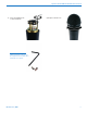
3) With a small screwdriver (included with your unit),
set the Frequency Switches to “CC” (for Change,
Change).
IMPORTANT: When performing the following
steps, The transmitter allows ten seconds to
set the frequency switches before the next
toggle of the power switch. When toggling the
power switch, it is not neccesary to allow the
transmitter to turn off completely. If more than
ten seconds elapse between toggles, the mode
change will not take effect and you must begin
again from step 3.
Operating Instructions
4) Rapidly toggle the Power Switch Off and On.
Change the Frequency Switches to one of the fol-
lowing settings:.
•100Seriesmode: 1,1
•200Seriesmode: 2,2
•Mode3: 3,3
•400Seriesmode: 4,4
•IFBSeriesmode: 5,5
5) Rapidly toggle the Power Switch Off and On.
Set the Frequency Switches to 0,0.
6) Rapidly toggle the Power Switch Off and On.
Observe the Power LED on the bottom panel to ver-
ify the compatibility mode for the unit has changed.
The Power LED will blink the new
compatibility mode. (See Step 2.)
Note: Each time the transmitter is turned on, the
Power LED will confirm the current operating mode
with the number of blinks listed in Step 2. The
mode setting will not change until it is reset with
the procedure listed above.
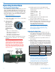
Adjusting the Audio Gain
1) Install a good battery in the transmitter. Move the
Power Switch to On and observe the Power LED. It
should blink the compatibility mode, then glow green.
2) Set the Attenuator control to “F” before adjusting the
input gain.
3) Hold the microphone the way it will be used in ac-
tual operation.
4) While speaking or singing at the same voice level
that will actually be used during the program. Adjust
the Audio Level control while observing the Modula-
tion LEDs until the –20 dB LED occasionally flickers
red and the -10 dB glows green.
Signal Level -20 LED -10 LED
Less than -20 dB
Off
Off
-20 dB to -10 dB
Green Off
-10 dB to +0 dB
Green Green
+0 dB to +10 dB
Red Green
Greater than +10 dB
Red Red
Note: If the Audio Level control is at minimum
and both Modulation LEDs still blink red
frequently, then additional attenuation is needed.
Unscrew the windscreen and carefully lift it off
the top of the unit. Rotate the Attenuator control
counterclockwise from “F” one step at a time until
the Modulation LEDs indicate at the desired level.
5) Once the audio gain has been set, the signal
can be sent through the sound system for
overall level adjustments, monitor settings, etc.
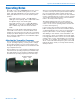
Power LED
Power Switch
0
1
2
3
4
5
6
7
8
9
A
B
C
D
E
F
0
1
2
3
4
5
6
7
8
9
A
B
C
D
E
F
Modulation LEDs
-20 -10
Audio Level
Control
Frequency Switches
Coarse Fine