
User Manual


10
UT400
LECTROSONICS, INC.
OPERATING INSTRUCTIONS
SELECTING THE OPERATING MODE
All units with serial number 601 and up are capable of working with Lectrosonics 100 series analog , 200 series analog,
400 series digital hybrid or some other analog wireless receivers (contact the factory for details). The transmitter must
be set to the operating mode of the matching receiver, which is easily done using only the supplied screwdriver and a
battery.
NOTE: the unit is supplied from the factory as a 400 series transmitter
1) Make certain a good battery is installed.
2) Power down the transmitter.
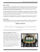
3) With a small screwdriver (included with your unit), set the frequency change switches to CC. (for Change, Change).
4) Power up the unit briefly – just a couple of seconds (just watch for the LED’s to light up) and then turn it off.
5) Change the switches to one of the following settings:
• To set Lectrosonics 100 mode: set switches to 1,1
• To set Lectrosonics 200 mode: set switches to 2,2
• To set mode 3: set switches to 3,3* (contact the factory for details)
• To set Lectro digital hybrid (400) mode: set switches to 4,4
6) Turn the unit on, wait just a couple of seconds and turn off again.
7) Change the switches to 0,0.
8) Power up the unit – you have now changed the operation mode for the unit.
The LEDS will blink at powerup to indicate the selected operating mode. Immediately after powering up, all LEDS
will blink together red, then green, followed by the audio level LEDs (-20 and -10) blinking to indicate the mode.
The –20 and –10 LEDs will blink:
• Once for 100 mode
• Two times for 200 mode
• Three times for some other receivers
• Four times for 400 mode
At powerup the transmitter will confirm the current operating mode with the number of blinks listed here. The setting
will remain the same until you reset it with the procedure listed above.
ADJUSTING THE GAIN
1) Install a fresh battery. Leave the battery cover off for further adjustment.
2) On the bottom panel, move the “A” (audio) switch to “OFF” (away from the LED) and the “P” (power) switch to ON
(toward the LED) in that order. Observe that the battery status LED is brightly lit. If the LED is dim, replace the
battery.
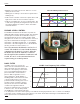
3) Hold the microphone in the same position that it will be used in actual operation.
4) While speaking or singing at the same voice level that will actually be used, observe the MODULATION LEDs.
Adjust the AUDIO LEVEL control knob until the LEDs begin to light. At too low a setting neither LED will light as
you speak. Gradually, turn the gain up until the –20 dB LED lights green and then the -10 dB lights green. We
strongly recommend setting the gain of the transmitter even higher so that the first red LED occasionally lights.
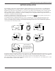
If you find that the AUDIO LEVEL control is set to minimum and the LIMIT LED is still on often, then adjust the
attenuator. This control is located under the windscreen. Unscrew the windscreen and carefully lift it off the top of
the unit. See the VERIMIC CONTROLS section for these adjustments. If you need to change these controls, be
sure to repeat the gain adjustment procedure beginning at step 3.
5) Once the gain has been adjusted, the audio system audio can be turned on to make level adjustments in the main
audio system.