INSTRUCTION MANUAL UT Synthesized UHF Hand-Held Transmitter Featuring Digital Hybrid Wireless® Technology* *US Patent 7,225,135 Fill in for your records: Serial Number: Purchase Date: Rio Rancho, NM, USA www.lectrosonics.
UT 2 LECTROSONICS, INC.
Synthesized UHF Hand-Held Transmitter Table of Contents General Technical Description ..............................................................................................................................................................4 Introduction ...........................................................................................................................................................................................4 Digital Hybrid Technology .....................................
UT General Technical Description Introduction The UT Digital Hybrid Wireless™ handheld transmitter uses state-of-the-art wireless technology with a highpowered 100mW RF output and a unique microphone capsule arrangement. The VariMic™ preamp allows the user to custom-tailor the microphone’s response to suit the application. Three capsules are available for this transmitter: a cardi oid condenser, an omni condenser and a super-cardioid condenser.
Synthesized UHF Hand-Held Transmitter Compatibility Modes The transmitter was designed to operate with Lectro sonics Digital Hybrid Wireless™ receivers and will yield the best performance when doing so. However, due to the flexibility of digital signal processing, it is also able to operate with Lectrosonics 200 Series, Lectrosonics 100 Series, IFB and certain non-Lectrosonics analog receivers in special compatibility modes.
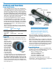
UT Controls and Functions Power On/Off Switch A Power On/Off switch located on the outside bottom of the unit turns the unit on and off. The function of the Power On/Off Switch can also be changed so it also operates as an audio mute switch. In this configuration, the Power LED doubles as a battery status indicator (in the unmute or On position) and an audio mute/unmute indicator (in the muted or Off position). (See Operating Instructions, Power Switch Function Selection.
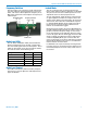
Synthesized UHF Hand-Held Transmitter Frequency Switches Two 16-position rotary switches (located under the bat tery door) adjust the operating frequency of the trans mitter. The Coarse switch adjusts the frequency in 1.6 MHz steps and the Fine switch adjusts the frequency in 100 kHz steps.
UT VariMic™ Controls Caution: Due to the high RF levels surrounding the transmitter, the sound of the VariMicTM capsule may be temporarily affected if the metal windscreen is not in place. Always make the final decision about sound balance and quality with the windscreen in place. The VariMicTM head includes adjustments for Bass (LO), Midrange (MID) and Treble (HI) response. There is also an attenuation adjustment to provide up to 15 dB of ad ditional headroom if needed.
Synthesized UHF Hand-Held Transmitter Subsonic Noise Filter In addition to the tone controls, the UT also has a builtin subsonic noise (or high pass) filter. This filter is fixed and cannot be adjusted or defeated. Low frequency noise is much more of a problem with wireless micro phones than with conventional microphones.
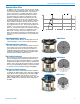
UT Changing Capsules 1) Remove windscreen 3) Lift capsule assembly 2) Loosen and remove the two screws that attach the capsule to the micro phone body 4) Disconnect 3-pin con nector Caution: Avoid damaging the coiled wire under the capsule. 5) Connect new capsule 10 6) Set new capsule assembly to align the holes for the socket head bolts LECTROSONICS, INC.
Synthesized UHF Hand-Held Transmitter 7) Insert and tighten both socket head screws 8) Replace windscreen The latest mounting kit includes hex head screws and lock washers. These replace earlier types of screws and Vibratite (Loctite) sealer.
UT Operating Instructions Selecting Compatibility Mode 4) Rapidly toggle the power switch On and then OFF. This transmitter is capable of working with Lectrosonics 400 Series Digital Hybrid Wireless™, 200 Series, 100 Series, and some analog wireless receivers from other manufacturers. (Contact Lectrosonics for details.) The transmitter must be set for compatibility with the match ing receiver, which is easily done using the supplied screwdriver and a battery.
Synthesized UHF Hand-Held Transmitter 5) Once the audio gain has been set, the signal can be sent through the sound system for overall level adjustments, monitor settings, etc. Power ON/OFF Switch Function Selection The Power On/Off switch can be configured as an audio mute switch. When used as an audio mute switch, the power switch causes the transmitter’s audio to be muted when the switch is placed in the Off position.
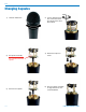
UT Battery Installation The transmitter is powered by a standard alkaline or lithium 9 Volt battery. Alkaline batteries will provide about 3.5 hours of operation while the lithium batteries will operate the transmitter for about 6.5 hours. Note: The battery status lamp will function normally only with alkaline or lithium batteries. Standard zinc-carbon batteries marked “heavy duty” or “long lasting” are not adequate. They will provide only about 30 minutes of operation.
Synthesized UHF Hand-Held Transmitter Operating Notes The Audio Level control should not be used to control the volume of the overall sound system or recorder levels. This gain adjustment is used to match the trans mitter gain with the user’s voice level and microphone position. If the audio level is too high — both Modulation LEDs glow red sporadically. This condition will reduce the dynamic range of the audio signal.
UT Troubleshooting SYMPTOM POSSIBLE CAUSE UT POWER LED OFF 1) Battery is inserted backwards. 2) Battery is dead, or too low to be used. UT MODULATION LEDs OFF 1) Audio Level control turned all the way down. 2) Battery is in backwards. Check Power LED. 3) Mic capsule is damaged or malfunctioning. Contact the factory for repair . 4) Attenuator on VariMic™ preamp board is set for too much attenuation. RECEIVER RF INDICATOR OFF 1) 2) 3) 4) UT not turned on.
Synthesized UHF Hand-Held Transmitter Specifications Operating frequencies: Frequency selection: Channel Separation: RF Power output: Pilot tone: Frequency stability: Deviation: Spurious radiation: Input limiter: Gain control range: Modulation indicators: Block 21 Block 22 Block 23 537.600 - 563.100 563.200 - 588.700 588.800 - 607.900 and 614.100 - 614.300 Block 24 614.400 - 639.900 Block 25 640.000 - 665.500 Block 26 665.600 - 691.100 Block 27 691.200 - 716.700 Block 28 716.800 - 742.300 Block 29 742.
UT Service and Repair If your system malfunctions, you should attempt to correct or isolate the trouble before concluding that the equipment needs repair. Make sure you have followed the setup procedure and operating instructions. Check the interconnect ing cables and then go through the Troubleshooting section in this manual. We strongly recommend that you do not try to repair the equipment yourself and do not have the local repair shop attempt anything other than the simplest repair.
Synthesized UHF Hand-Held Transmitter Rio Rancho, NM 19
14 July 2011