UT200C FREQUENCY-AGILE HAND-HELD TRANSMITTER OPERATING INSTRUCTIONS and trouble-shooting guide LECTROSONICS, INC. Rio Rancho, NM www.lectrosonics.
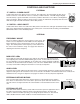
INTRODUCTION Thank you for selecting the Lectrosonics UT200C hand-held wireless transmitter. The UT combines over 80 years of engineering experience with the very latest components in a design that addresses the most demanding professional applications. The design of the UT200C was the direct result of numerous conversations with users, staging and touring companies and dealers across the US.
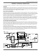
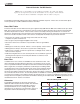
Frequency Agile Handheld Transmitter GENERAL TECHNICAL DESCRIPTION The UT200C transmitters are comprised of a number of functional sub-systems as shown in the block diagram below. GENERAL The 200 system uses 75kHz wide deviation for an extremely high signal to noise ratio. The transmitter circuits are all regulated to allow full output power from the beginning (9 Volts) to the end (7 Volts) of battery life. The input amplifier uses a Motorola 33078 op amp for ultra low noise operation.
PILOT TONE SQUELCH The 200 system utilizes an ultrasonic tone modulation of the carrier to operate the receiver squelch. This “pilot tone” consists of a 32kHz signal mixed with the audio signal following the microphone preamp, just after the compandor, to control the audio output muting of the receiver. The pilot tone is filtered out of the audio signal immediately after the detector in the receiver so that it does not influence the compandor or various gain stages.
Frequency Agile Handheld Transmitter CONTROLS AND FUNCTIONS EXTERNAL “P” SWITCH – POWER ON/OFF A slide switch which turns battery power on and off. The LED next to the switch lights up when the “P” switch is turned on. This LED also serves as a battery condition indicator. The LED will glow brightly when the battery is good and will dim as the battery condition deteriorates. The LED is at full brightness with a new battery. When the battery voltage reaches 7 Volts, the LED will be completely dark.
Internal Controls - VariMic Version Caution - Due to the high RF levels surrounding the transmitter, the sound of the Varimic capsule may be temporarily affected if the metal windscreen is not in place. Always make the final decision about sound balance and quality with the windscreen in place. The VariMic head includes adjustments for Bass, Midrange and Treble response. There is also an attenuation adjust ment to provide up to 15dB of additional headroom if needed.
Frequency Agile Handheld Transmitter attenuation or the highest signal level. “0” is maximum attenuation or the lowest signal level. For the maximum amount of headroom, set the switch to “0.” Note: The attenuator should not be used as a level control. The Audio Level control inside the battery compartment is the main level control. Adjust the attenuator only when the Audio Level control is turned completely down and more headroom is still needed.
BATTERY INSTALLATION The transmitter is powered by a standard alkaline 9 Volt battery. It is important that you use ONLY ALKALINE or LITHIUM batteries for reliable operation. Alkaline batteries will provide about 4 hours of operation while the lithium batteries will operate the transmitter for over 12 hours. The battery status lamp will function normally only with alkaline or lithium batteries. Standard zinc-carbon batteries marked “heavy duty” or “long-lasting” are not adequate.
Frequency Agile Handheld Transmitter OPERATING INSTRUCTIONS 1) Install a fresh battery according to the instructions on page 8. Leave the battery cover off for further adjustment. 2) Set the internal bypass slide switches so that the battery status LED and the bottom panel switches will operate. 3) On the bottom panel, move the “A” (audio) switch to “OFF” (away from the LED) and the “P” (power) switch to ON (toward the LED) in that order. Observe that the battery status LED is brightly lit.
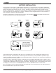
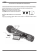
ADJUSTING THE TRANSMITTER FREQUENCY If you are experiencing interference from another signal on your frequency, you may want to change the operating frequency of your system. The switch nearest to the mic element changes the operating frequency by 100 kHz per step and the switch furthest from the mic element changes it 1.6 MHz per step. If you are experiencing interference, change the operating frequency of the receiver to find a clear channel, then set the transmitter to match.
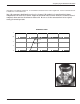
Frequency Agile Handheld Transmitter TROUBLESHOOTING Before going through the following chart, be sure that you have a good battery in the transmitter. It is important that you follow these steps in the sequence listed. SYMPTOM POSSIBLE CAUSE TRANSMITTER BATTERY LED OFF 1) External LED is turned off. Check internal slide switch. 2) Battery is inserted backwards. 3) Battery is dead, or too low to be used. NO TRANSMITTER MOD LEVEL LEDs 1) Gain control turned all the way down. 2) Battery is in backwards.
SPECIFICATIONS Operating Frequencies: 537.600 to 607.900 MHz 614.100 to 767.900 MHz RF Power Output: 100mW Pilot Tone: 32.765 kHz, ±2 Hz, 5kHz deviation Frequency Stability: ±0.
Frequency Agile Handheld Transmitter SERVICE AND REPAIR If your system malfunctions, you should attempt to correct or isolate the trouble before concluding that the equipment needs repair. Make sure you have followed the setup procedure and operating instructions.
LIMITEDONE ONE YEAR WARRANTY LIMITED YEAR WARRANTY The equipment is warranted for one year from date of purchase against defects in materials or workmanship provided it was purchased from an authorized dealer. This warranty does not cover equipment which has been abused or damaged by careless handling or shipping. This warranty does not apply to used or demonstrator equipment. Should any defect develop, Lectrosonics, Inc.