UR195 COMPACT UHF RECEIVER OPERATING INSTRUCTIONS and troubleshooting guide LECTROSONICS, INC.
Table of Contents INTRODUCTION TO THE 195 SYSTEM .............................................................. 3 UT195 TRANSMITTER .......................................................................................................... UM195 TRANSMITTER ......................................................................................................... DUAL-BAND COMPANDOR ................................................................................................. 75kHz DEVIATION ...............
INTRODUCTION TO THE 195 SYSTEM The 195 Series system was designed for the most critical studio and sound reinforcement applications. The system design represents a significant step forward in wireless microphone technology. Every stage in the entire audio/radio chain from transmitter input to receiver output was evaluated and analyzed to produce the operating parameters and performance requirements for this entirely new design.
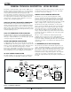
GENERAL TECHNICAL DESCRIPTION - UR195 RECEIVER The UR195 is a high performance, dual-conversion, UHF receiver. The RF performance is extremely stable over a very wide tempera ture range, making the UR195 perfectly suited to the rough environ mental conditions found in the field. The proprietary audio processing includes a dual-band compandor for very low distortion and a superior signal to noise ratio.
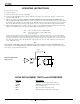
The audio signal leaves the Detector circuit and is fed through an amplifier to the 23 kHz Low Pass Filter where all the high frequency noise (including the 32 kHz pilot tone) is filtered out. After the 23 kHz low pass filter, the signal is split into two parts via a 1 kHz low pass filter and a 1 kHz high pass filter. The separated signals are then processed in separate channels of the NE572 2:1 Expander. Each channel of the 2:1 Expander is optimized for its respective frequency band.
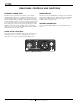
REAR PANEL CONTROLS AND FUNCTIONS EXTERNAL POWER JACK RANGE SWITCH The UR195 can be powered from external 12 to 18 Volts DC applied directly to this jack, or conventional 110 VAC sources via the supplied CH12 adapter. The UR195 is protected from reverse polarity conditions with a diode bridge which allows external DC to be applied without regard to polarity.
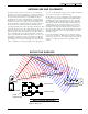
ANTENNA USE AND PLACEMENT Position the antenna so that it is more than 3 or 4 feet from large metal surfaces. If this is not possible, try to position the antenna so that it is as far away from the metal surface as is practical. You can also let the metal surface work for you by aligning the antenna perpendicular to the surface. This will provide a ground plane for the antenna.
OPERATING INSTRUCTIONS 1. Connect the power cord. 2. Attach the antenna. 3. Connect the audio cable to the audio output XLR. 4. Set the front panel Audio Output Level control to minimum and set the Power switch to On. Check to see that the front panel Power LED lights up. 5. Adjust the transmitter gain. THIS IS PERHAPS THE MOST IMPORTANT STEP IN THE SET UP PROCEDURE. See your transmitter manual (Operating Instructions section) for details on how to adjust the transmitter gain.
TROUBLESHOOTING POWER SUPPLY AND FUSE LEDs not lit or dimly lit AC power cord disconnected. External power supply disconnected or inadequate. Main power supply fuse tripped. Turn the receiver off, remove the cause of the overload and turn the receiver back on. PILOT TONE SQUELCH The PILOT indicator lamp on the front panel lights up to indicate that the audio has been turned on at the transmitter, and that the audio output on the receiver is enabled. When the lamp is on, the audio is enabled.
SERVICE AND REPAIR If your system malfunctions, you should attempt to correct or isolate the trouble before concluding that the equipment needs repair. Make sure you have followed the setup procedure and operating instructions. Check out the inter-connecting cords and then go through the TROUBLE SHOOTING section in the manual We strongly recommend that you do not try to repair the equipment yourself and do not have the local repair shop attempt anything other than the simplest repair.
SPECIFICATIONS AND FEATURES Receiver Operating Frequencies: 470 to 608 MHz, crystal controlled Receiver Type: Dual conversion, superheterodyne Frequency Stability: ±0.002 % Front end selectivity: -22 dB at ±4 MHz IF Selectivity: >90 dB at ±300 kHz (10.7 IF) IF Frequency: 10.7 MHz (1st IF); 455 kHz (2nd IF) IF bandwidth: ±150 kHz at ½ power points Sensitivity 20 dB Sinad: 0.63 uV (-111 dBm), A weighted 60 dB Quieting: 1.
LIMITED ONE YEAR WARRANTY The equipment is warranted for one year from date of purchase against defects in materials or workmanship provided it was purchased from an authorized dealer. This warranty does not cover equipment which has been abused or damaged by careless handling or shipping. This warranty does not apply to used or demonstrator equipment. Should any defect develop, we will, at our option, repair or replace any defective parts without charge for either parts or labor.