UMC 16A RF DISTRIBUTION SYSTEM OPERATING INSTRUCTIONS and trouble-shooting guide Rio Rancho, NM, USA www.lectrosonics.
INTRODUCTION The UMC16 multi-coupler combines ceramic filtering with low noise, high intercept point RF distribution to provide outstanding performance and flexibility. Up to eight diversity receivers or up to 16 non-diversity receivers can be utilized in up to a 50MHz passband. The UMC16 can be powered by 110V AC for stage, studio or installed system applications, or from DC power for field operation. Table of Contents INTRODUCTION ..........................................................................
GENERAL TECHNICAL DESCRIPTION A universal power supply provides operation world-wide. An LED on the front panel verifies the presence of power to the internal circuit board. Selective filtering ahead of the low noise, high intercept RF amplifiers reduces intermodulation problems caused by overload in the RF amplifiers. The filters provide a factory settable bandwidth of 16 to 50MHz. Note: The frequency range and bandwidth is set at the factory and can be found by the serial number on the rear of the unit.
REAR PANEL DESCRIPTION ANT B RF OUT RF OUT 12V DC IN 400MA MAX ANT A UMC16A S/N 0000 000-111 MHz 100 - 240 VAC 10 WATTS Figure 3 - UMC16a Rear Panel ANT A / ANT B RF input jacks. These are standard BNC, quarter-turn twist lock connectors. Each antenna jack is completely separate from the other. RF OUT RF output to receiver antenna jack(s). Each group of RF outputs is completely separate from the other. 12V DC IN Alternate power input jack. The UMC16 can accept any DC voltage from +11 to +14.V DC.
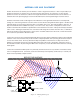
ANTENNA USE AND PLACEMENT Position the antennas so that they are not within 3 or 4 feet of large metal surfaces. If this is not possible, try to position the antennas so that they are as far away from the metal surface as is practical. It is also good to position the receiver so that there is a direct “line of sight” between the transmitter and the receiver antenna. In situations where the operating range is less than about 50 feet, the antenna positioning is much less critical.
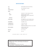
SPECIFICATIONS Type: Active RF distribution system with ceramic filtering Inputs: Two 50 Ohm BNC jack on rear panel Third order intercept: +27dBm at input Outputs: Type: 16 BNC jacks on rear panel. Eight jacks per antenna. Isolation: 25dB min, any output to any output Any output can be open, shorted, or terminated without affecting other outputs.
SERVICE AND REPAIR If your system malfunctions, you should attempt to correct or isolate the trouble before concluding that the equip ment needs repair. Make sure you have followed the setup procedure and operating instructions. Check out the inter-connecting cords and then go through the TROUBLE SHOOTING section in the manual We strongly recommend that you do not try to repair the equipment yourself and do not have the local repair shop attempt anything other than the simplest repair.
LIMITED ONE YEAR WARRANTY The equipment is warranted for one year from date of purchase against defects in materials or workmanship provided it was purchased from an authorized dealer. This warranty does not cover equipment which has been abused or damaged by careless handling or shipping. This warranty does not apply to used or demonstrator equipment. Should any defect develop, Lectrosonics, Inc. will, at our option, repair or replace any defective parts without charge for either parts or labor.