UM700 ENCRYPTED DIGITAL UHF BELT-PACK TRANSMITTER OPERATING INSTRUCTIONS and trouble-shooting guide LECTROSONICS, INC. Rio Rancho, NM www.lectrosonics.
UM700 TABLE OF CONTENTS INTRODUCTION ................................................................................................... 3 GENERAL TECHNICAL DESCRIPTION ............................................................. 4 CONTROLS AND FUNCTIONS ........................................................................... 6 BATTERY INSTALLATION .................................................................................... 8 OPERATING INSTRUCTIONS .............................................
Digital Frequency Agile UHF Belt-Pack Transmitter INTRODUCTION The 700 Series wireless system provides a combination of outstanding audio quality and secure encryption. This unique combination makes the 700 Series equally suitable for high-end studio and stage applications, and for corporate and govern ment applications where security is a concern. Several advantages are provided by a digital wireless system: • A digital radio system provides outstanding signal to noise ratio.
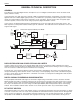
UM700 GENERAL TECHNICAL DESCRIPTION GENERAL The 700 series encrypted digital wireless microphones use an all-digital communications link for excellent sound quality and data security. In the transmitter, the audio first passes through a DSP-controlled dual envelope analog limiter. The signal is then digitized and fed to a DSP (digital signal processor). The DSP uses a proprietary audio encoding scheme to lower the bit rate and provide the high entropy required for secure encryption.
Digital Frequency Agile UHF Belt-Pack Transmitter tenna. The circular isolator functions like a “one-way check valve” to allow the RF signal to pass through to the antenna, but not to pass backwards into the amplifier stage. RF signals from other nearby transmitters cannot reach the output amplifier in the UM700. This provides excellent stability and eliminates IM in the output stage of the transmitter.
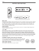
UM700 CONTROLS AND FUNCTIONS LECTROSONICS UM700 FREQUENCY E D C B A F 0 1 2 3 4 5 9 8 7 6 E D C B A F 0 1 1.6MHz 100kHz 2 3 4 5 9 8 7 6 OFF ON AUDIO LEVEL –10 –20 75 Hz ANTENNA 35 150 LF ROLL OFF FCCID:DBZUM700 Lectrosonics, Inc. Made in U.S.A. SN: XXXX INPUT JACK The input jack on the UM700 is a Switchcraft TA5M connector that accommodates virtually every lavaliere, hand-held or shotgun microphone available, with positive or negative bias.
Digital Frequency Agile UHF Belt-Pack Transmitter MODULATION LEDS Indicate the proper setting of the MIC LEVEL control. There are two bicolor modulation LEDs that can light either red or green. “-20dB level” One modulation LED glows green and the transmitter is 20 dB below full modulation. “-10 dB level” “+0 dB level” Both modulation LEDs glow green and the transmitter is close to full modulation. The -20 LED glows red and the -10 LED glows green.
UM700 BATTERY INSTALLATION The transmitter is powered by a standard alkaline or lithium 9 Volt battery. It is important that you use ONLY an ALKALINE or LITHIUM battery for longest life. Standard zinc-carbon batteries marked “heavy-duty” or “long lasting” are not adequate. Ni-cad rechargeable batteries will only provide 1.5 hours of operation, or less, and will run down quite abruptly. Unless it is cold, alkaline batteries provide over 4.5 hours of operation.
Digital Frequency Agile UHF Belt-Pack Transmitter OPERATING INSTRUCTIONS 1) Install a fresh battery according to the instructions above. 2) Insert the microphone plug into the input jack, aligning the pins; be sure that the connector locks in. 3) Attach the antenna to the SMA connector on the top of the transmitter. 4) Mute the sound system. 5) Turn the transmitter power switch to the “ON” position. Note: If the security level is set to “2”, the receiver must be powered on before the transmitter.
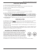
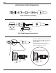
UM700 MICROPHONE CORD TERMINATION TA5F Connector Assembly 1 4 5 2 3 VIEW FROM SOLDER SIDE OF PINS 0.15" 0.3" Heatshrink Tubing Mic Cord Stripping Instructions Be sure the shield wire touches the metal crimp tab. This helps prevent any AM component of the transmitter signal from entering the mic and causing a "whine." Note that this is opposite from our VHF transmitter wiring where the shield should not touch any metal part of the housing. This is the correct way.
Digital Frequency Agile UHF Belt-Pack Transmitter 5-PIN INPUT JACK WIRING The wiring diagrams shown on the next page represent the basic wiring necessary for the most common types of microphones and other audio inputs. Some microphones may require extra jumpers or a slight variation on the diagrams shown. It’s virtually impossible to keep completely up to date on changes that other manufacturers make to their products. It is possible that you may encounter a microphone that differs from these instructions.
UM700 RF BYPASSING 2 WIRE MIC Some mics require RF protection to keep the radio signal from affecting the capsule, even though the transmitter input circuitry is already RF bypassed (see schematic diagram). If the mic is wired as directed, and you are having difficulty with squealing, high noise, or poor frequency response; RF is likely to be the cause.
Digital Frequency Agile UHF Belt-Pack Transmitter TROUBLESHOOTING Before going through the following chart, be sure that you have a good battery in the transmitter. It is important that you follow these steps in the sequence listed. SYMPTOM POSSIBLE CAUSE TRANSMITTER BATTERY LED OFF 1) Battery is inserted backwards. 2) Battery is dead.
UM700 SPECIFICATIONS AND FEATURES Operating principle: Modulation type: Sample rate: Audio coder: Encryption key length: Bit rate: Operating frequencies: Frequency selection: RF Power output: Frequency stability: Equivalent input noise: Spurious radiation: Input Level: Input impedance: Input compressor: Gain control range: Modulation indicators: Low frequency roll-off adjustment: Controls: Proprietary digital modulation with encryption Modified pi/4 DQPSK 44.
Digital Frequency Agile UHF Belt-Pack Transmitter SERVICE AND REPAIR If your system malfunctions, you should attempt to correct or isolate the trouble before concluding that the equipment needs repair. Make sure you have followed the setup procedure and operating instructions.
LIMITEDONE ONE YEAR WARRANTY LIMITED YEAR WARRANTY The equipment is warranted for one year from date of purchase against defects in materials or workmanship provided it was purchased from an authorized dealer. This warranty does not cover equipment which has been abused or damaged by careless handling or shipping. This warranty does not apply to used or demonstrator equipment. Should any defect develop, Lectrosonics, Inc.