
User's Manual


Frequency-Agile UHF Belt-Pack Transmitter
Rio Rancho, NM 7
No Pre-Emphasis/De-Emphasis
The signal to noise ratio of the 400 system is high
enough to preclude the need for conventional pre-
emphasis (HF boost) in the transmitter and de-empha-
sis (HF roll off) in the receiver. Pre-emphasis and de-
emphasis in an FM radio system usually provides about
a 10 dB improvement in the signal to noise ratio of the
system, but the high frequency boost in the transmitter
must be removed in a purely complementary manner or
else the frequency response of the original audio signal
will be altered.
Pre-emphasis can also cause distortion in the receiver.
As this signal is passed through the IF filters in the
receiver, distortion can be produced, most noticeably at
full modulation. De-emphasis cannot be applied until
the signal is converted into audio, so there is no way
around this problem short of eliminating pre-emphasis
altogether. Neither of these problems occur in the 400
system
Pilot Tone Squelch
The 400 system uses one of 256 different ultrasonic
tones between 25 and 32 kHz, that modulate the
carrier to operate the receiver squelch. The pilot tone
frequency is chosen according to which of the 256
channels has been selected by the frequency switch
setting. The basic benefit of the pilot tone squelch
system is that the receiver will remain muted until it
receives the pilot tone from the matching transmitter,
even if a strong RF signal is present on the carrier
frequency of the system. The UM450 extends this
concept even further by insuring that all transmitters in
a system have different pilot tone frequencies so that
even spurious RF from the wrong transmitters can’t
open the receiver squelch.
Input Limiter
The 400 series transmitters employ a digitally-controlled
analog audio limiter just before the analog-to-digital
converter. The limiter has a range of more than 30 dB
for excellent overload protection. A dual release
envelope makes the limiter acoustically transparent
while maintaining low distortion. It can be thought of as
two limiters in series, connected as a fast attack and
release limiter followed by a slow attack and release
limiter. The limiter recovers quickly from brief tran-
sients, so that its action is hidden from the listener, but
recovers slowly from sustained high levels, to both keep
audio distortion low and preserve short term dynamic
changes.
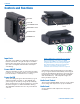
The audio level LEDs indicate limiter activity. The first
red LED indicates that the limiter is active and that the
transmitter is fully modulated (audio level is between +0
and +10 dB). The second red LED indicates that the
level is 10 dB or more into limiting. Occasional forays
into the red are desirable for most applications, since
the distortion introduced by the limiter is so minimal,
and full modulation is thus assured. We strongly
recommend setting the gain of the transmitter high
enough so that the first red LED occasionally lights.
Generally speaking, some limiting is desirable in
normal operation to improve the signal to noise ratio of
the system. The limiting action is not audible and does
not create distortion. A highly trained ear would hear
only the compression of the peaks in the audio signal,
which is desirable with most recorders and many sound
reinforcement systems.
Wide-Band Deviation
± 75 kHz deviation improves the capture ratio, signal to
noise ratio and AM rejection of a wireless system
dramatically, compared to the more commonly used
±15 kHz deviation.
Long Battery life
Switching power supplies throughout the design allow
over ninety minutes of operation using a single 9 VDC
alkaline battery. (A 9 V lithium battery will provide over
4.5 hours of continuous operation.) The battery con-
tacts are spring loaded to prevent “rattle” as the unit is
handled.
Frequency Agility
The transmitter section uses a synthesized, frequency
selectable main oscillator. The frequency is extremely
stable over a wide temperature range and over time.
Two rotary switches, located on the side panel of the
unit, provide 256 frequencies in 100 kHz steps over a
25.5 MHz range. This alleviates carrier interference
problems in mobile or traveling applications.
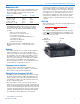
Antenna
The antenna on the UM450 consists of a flexible 1/4
wavelength galvanized steel cable, detachable via an
SMA connector. The impedance of this connector is 50
Ohms.