
User's Manual


UM450
LECTROSONICS, INC.
10
The wiring diagrams included in this section represent
the basic wiring necessary for the most common types
of microphones and other audio inputs. Some micro-
phones may require extra jumpers or a slight variation
on the diagrams shown.
It is virtually impossible to keep completely up to date
on changes that other manufacturers make to their
products, thus you may encounter a microphone that
differs from these instructions. If this occurs please call
our toll-free number listed under Service and Repair in
this manual or visit our web site at: http://www.lectro-
sonics.com
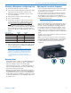
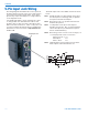
5-Pin Input Jack Wiring
Audio Input Jack
The Audio Input Jack for the UM450 is wired as shown
below:
PIN 1 Shield (ground) for positive biased electret lava-
liere microphones. Shield (ground) for dynamic
microphones and line level inputs.
PIN 2 Bias voltage source for positive biased electret
lavaliere microphones.
PIN 3 Low impedance microphone level input for
dynamic microphones. Also accepts hand-held
electret microphones provided the microphone
has its own built-in battery.
PIN 4 Bias voltage selector for Pin 3. Pin 3 voltage (0, 2
or 4 volts) depends on Pin 4 connection.
Pin 4 tied to Pin 1: 0 V
Pin 4 Open: 2 V
Pin 4 to Pin 2: 4 V
PIN 5 High impedance, line level input for tape decks,
mixer outputs, musical instruments, etc.