UM400 FREQUENCY-AGILE UHF BELT-PACK TRANSMITTER OPERATING INSTRUCTIONS and trouble-shooting guide LECTROSONICS, INC. Rio Rancho, NM www.lectrosonics.
TABLE OF CONTENTS INTRODUCTION ................................................................................................... 3 GENERAL TECHNICAL DESCRIPTION .............................................................. 4 CONTROLS AND FUNCTIONS ............................................................................ 6 BATTERY INSTALLATION .................................................................................... 8 OPERATING INSTRUCTIONS ...................................................
Frequency-Agile UHF Belt-Pack Transmitter INTRODUCTION Thank you for selecting the Lectrosonics UM400 frequency agile, belt-pack transmitter. The UM400 combines over 80 years of engineering experience with the very latest components, in a design that addresses the most demanding professional applications. The design of the UM400 was the direct result of numerous conversations with users, staging and touring companies and dealers across the US.
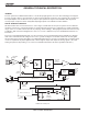
GENERAL TECHNICAL DESCRIPTION GENERAL The 400 system uses 75kHz wide deviation for an extremely high signal to noise ratio. The switching power supplies provide constant voltages to the transmitter circuits from the beginning (9.3 Volts) to the end (5.5 Volts) of battery life. The input amplifier uses an ultra low noise op amp for quiet operation. It is gain controlled with a wide range dual envelope input compressor which cleanly limits input signal peaks over 30dB above full modulation.
Frequency-Agile UHF Belt-Pack Transmitter Channel noise still has an impact on received signal quality and will eventually overwhelm the receiver. The Digital Hybrid simply encodes the signal to use a noisy channel as efficiently and robustly as possible, yielding audio performance that rivals that of wholly digital systems, without the power and bandwidth problems inherent in digital transmission. As always, these advantages come at a cost.
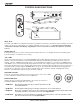
CONTROLS AND FUNCTIONS 100K LECTROSONICS E D C B A F 0 1.6M 1 2 3 4 5 9 8 7 6 E D C B A F 0 FREQUENCY 1 2 3 4 5 9 8 7 6 UM400 FREQUENCY ADJUST OFF ON AUDIO LEVEL 0 –20 LF ROLL-OFF ADJUST 75 Hz ANTENNA 35 150 LF ROLL OFF INPUT JACK The input on the UM400 accommodates virtually every lavaliere, hand-held or shotgun microphone available. Line level signals can also be accommodated. Use a Switchcraft TA5F connector on the cord.
Frequency-Agile UHF Belt-Pack Transmitter Input Limiter The 400 series transmitters employ a digitally-controlled analog audio limiter just before the analog-to-digital converter. The limiter has a range of more than 30dB for excellent overload protection. A dual release envelope makes the limiter acoustically transparent while maintaining low distortion. It can be thought of as two limiters in series, connected as a fast attack and release limiter followed by a slow attack and release limiter.
BATTERY INSTALLATION The transmitter is powered by a standard alkaline or lithium 9 Volt battery. It is important that you use ONLY an ALKALINE or LITHIUM battery for longest life. Standard zinc-carbon batteries marked “heavy-duty” or “longlasting” are not adequate. Ni-cad rechargeable batteries will only provide 1.5 hours of operation, or less, and will run down quite abruptly. Alkaline batteries provide over 5 hours of operation. Lithium batteries can be used to provide up to 16 hours.
Frequency-Agile UHF Belt-Pack Transmitter 7) While speaking or singing at the same voice level that will actually be used, observe the MODULATION LEDs. Adjust the AUDIO LEVEL control knob until the LEDs begin to light. At too low a setting neither LED will light as you speak. Gradually, turn the gain up until the –20 dB LED lights green and then the -10 dB lights green. We strongly recommend setting the gain of the transmitter even higher so that the first red LED occasionally lights.
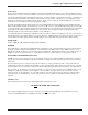
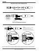
MICROPHONE CORD TERMINATION TA5F Connector Assembly 1 4 5 2 3 VIEW FROM SOLDER SIDE OF PINS 0.15" 0.3" Heatshrink Tubing Mic Cord Stripping Instructions Caution! Do not allow the shield wire to touch any metal part of the connector shell. The shield wire is the antenna on VHF models and poor operating range will result. Rubber Insulation Crimp Tabs Crimp Tabs Rubber Insulation Shield Wire Note: This termination is required on VHF transmitters and will still work fine on UHF transmitters.
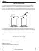
Frequency-Agile UHF Belt-Pack Transmitter 5-PIN INPUT JACK WIRING The wiring diagrams shown on the next page represent the basic wiring necessary for the most common types of microphones and other audio inputs. Some microphones may require extra jumpers or a slight variation on the diagrams shown. Caution - When wiring the connector, do not use the connector body for any electrical connections. A common mistake is to use the connector body as an audio ground.
RF BYPASSING Some mics require RF protection to keep the radio signal from affecting the capsule, even though the transmitter input circuitry is already RF bypassed (see schematic diagram). If the mic is wired as directed, and you are having difficulty with squealing, high noise, or poor frequency response; RF is likely to be the cause.
Frequency-Agile UHF Belt-Pack Transmitter TROUBLESHOOTING Before going through the following chart, be sure that you have a good battery in the transmitter. It is important that you follow these steps in the sequence listed. SYMPTOM POSSIBLE CAUSE TRANSMITTER BATTERY LED OFF 1) Battery is inserted backwards. 2) Battery is dead.
SPECIFICATIONS AND FEATURES Operating frequencies: 537.600 to 607.900 MHz 614.100 to 793.500 MHz Frequency selection: 256 frequencies in 100kHz steps RF Power output: 100 mW (nominal) Pilot tone: 25 to 30 kHz; 5kHz deviation Frequency stability: ± 0.002% Deviation: ± 75 kHz (max) Spurious radiation: 90 dB below carrier Equivalent input noise: –123 dBV Input level: Nominal 2 mV to 300 mV, before limiting. Greater than 1V maximum, with limiting.
Frequency-Agile UHF Belt-Pack Transmitter SERVICE AND REPAIR If your system malfunctions, you should attempt to correct or isolate the trouble before concluding that the equipment needs repair. Make sure you have followed the setup procedure and operating instructions.
LIMITEDONE ONE YEAR YEAR WARRANTY LIMITED WARRANTY The equipment is warranted for one year from date of purchase against defects in materials or workmanship provided it was purchased from an authorized dealer. This warranty does not cover equipment which has been abused or damaged by careless handling or shipping. This warranty does not apply to used or demonstrator equipment. Should any defect develop, Lectrosonics, Inc.