UM300B FREQUENCY-AGILE UHF BELT-PACK TRANSMITTER EURO MODEL OPERATING INSTRUCTIONS and trouble-shooting guide LECTROSONICS, INC. www.lectrosonics.
TABLE OF CONTENTS INTRODUCTION ................................................................................................... 3 GENERAL TECHNICAL DESCRIPTION ............................................................. 4 CONTROLS AND FUNCTIONS ........................................................................... 6 BATTERY INSTALLATION .................................................................................... 8 OPERATING INSTRUCTIONS ....................................................
Frequency Agile UHF Belt-Pack Transmitter INTRODUCTION Thank you for selecting the Lectrosonics UM300B frequency agile, belt-pack trans mitter. The UM300B combines over 80 years of engineering experience with the very latest components, in a design that addresses the most demanding professional applications. The design of the UM300B was the direct result of numerous conversations with users, staging and touring companies and dealers across the US.
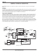
GENERAL TECHNICAL DESCRIPTION The UM300B transmitters are comprised of a number of functional sub-systems as shown in the block diagram below. GENERAL The 300 system uses 50kHz wide deviation for an extremely high signal to noise ratio. The transmitter circuits are all regulated to allow full output power from the beginning (9 Volts) to the end (6.5 Volts) of battery life. The input ampli fier uses a Motorola 33178 op amp for ultra low noise operation.
Frequency Agile UHF Belt-Pack Transmitter NO PRE-EMPHASIS/DE-EMPHASIS The signal to noise ratio of the 300 system is high enough to preclude the need for conventional pre-emphasis (HF boost) in the transmitter and de-emphasis (HF roll off) in the receiver.
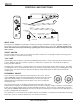
CONTROLS AND FUNCTIONS E D C B A F 0 LECTROSONICS FINE 1 2 3 4 5 9 8 7 6 E D C B A F 0 FREQUENCY COARSE 1 2 3 4 5 9 8 7 6 UM300B FREQUENCY ADJUST OFF ON AUDIO LEVEL 0 –20 LF ROLL-OFF ADJUST 75 Hz LECTRO UM300B - Int. App No: RO192WM Modulation Type: 180KF3E ANTENNA 35 150 LF ROLL OFF Freq. Range: 844.8 - 862 MHz Ser. No: XXXXXX - Block 33 INPUT JACK The input on the UM300B accommodates virtually every lavalier, hand-held or shotgun microphone available.
Frequency Agile UHF Belt-Pack Transmitter MODULATION LEDS Indicate the proper setting of the MIC LEVEL control. “-20” LED -- Flickers or glows when sufficient audio is present. “0” LED -- Lights up when the input level is high enough to cause limiting. The input limiter has a very high overload threshold (over 30 dB). Generally speaking, some limiting is desirable in normal operation to improve the signal to noise ratio of the system. The limiting action is not audible and does not create distor tion.
BATTERY INSTALLATION The transmitter is powered by a standard alkaline or lithium 9 Volt battery. It is important that you use ONLY an ALKALINE or LITHIUM battery for longest life. Standard zinc-carbon batteries marked “heavy-duty” or “long lasting” are not adequate. Ni-cad rechargeable batteries will only provide 1.5 hours of operation, or less, and will run down quite abruptly. Alkaline batteries provide over 7 hours of operation. Lithium batteries can be used to provide up to 17 hours.
Frequency Agile UHF Belt-Pack Transmitter 6) Position the microphone in the location you will use in actual operation. 7) While speaking or singing at the same voice level that will actually be used, observe the MODULATION LEDs. Adjust the AUDIO LEVEL control knob until the LEDs begin to light. Start at a low setting where neither LED lights as you speak. Gradually, turn the gain up until one LED lights, then the other. The -20 LED lights when the audio level is about 20dB below full modulation.
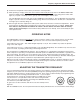
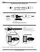
MICROPHONE CORD TERMINATION TA5F Connector Assembly 1 4 5 2 3 VIEW FROM SOLDER SIDE OF PINS 0.15" 0.3" Heatshrink Tubing Mic Cord Stripping Instructions Caution! Do not allow the shield wire to touch any metal part of the connector shell. The shield wire is the antenna on VHF models and poor operating range will result. Rubber Insulation Crimp Tabs Crimp Tabs Rubber Insulation Shield Wire Note: This termination is required on VHF transmitters and will still work fine on UHF transmitters.
Frequency Agile UHF Belt-Pack Transmitter 5-PIN INPUT JACK WIRING The wiring diagrams shown on the next page represent the basic wiring necessary for the most common types of microphones and other audio inputs. Some microphones may require extra jumpers or a slight variation on the diagrams shown. Caution - When wiring the connector, do not use the connector body for any electrical connections. A common mistake is to use the connector body as an audio ground.
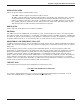
RF BYPASSING 2 WIRE MIC Some mics require RF protection to keep the radio signal from affecting the capsule, even though the transmitter input circuitry is already RF bypassed (see schematic diagram). 3 WIRE MIC Preferred locations for bypass capacitors SHIELD SHIELD If the mic is wired as directed, and you are having difficulty with squealing, high noise, or poor frequency response; RF is likely to be the cause.
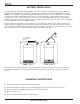
Frequency Agile UHF Belt-Pack Transmitter A6U UHF ANTENNA This is a full size cutting template. Lay the actual antenna on top of this drawing and cut at the mark for the desired frequency group. Install cap on end of antenna after cutting to length. Colored sleeve 21 22 23 24 25 26 28 27 30 29 32 33 31 Black cap Frequency Blocks Kits are shipped from the factory with caps of the various colors plus a black cap.
TROUBLESHOOTING Before going through the following chart, be sure that you have a good battery in the transmitter. It is important that you follow these steps in the sequence listed. SYMPTOM POSSIBLE CAUSE TRANSMITTER BATTERY LED OFF 1) Battery is inserted backwards. 2) Battery is dead. NO TRANSMITTER MODULATION LEDs 1) Gain control turned all the way down. 2) Battery is in backwards. Check power LED. 3) Mic capsule is damaged or malfunctioning. 4) Mic cable damaged or mis-wired.
Frequency Agile UHF Belt-Pack Transmitter SPECIFICATIONS AND FEATURES Operating frequencies: Frequency selection: RF Power output: Pilot tone: 525.000 to 862.00 MHz Up to 256 frequencies 50 mW (nominal) 32.764 kHz (± 2Hz); 5kHz deviation Frequency stability: Deviation: Spurious radiation: Equivalent input noise: ± 0.002% ± 50 kHz (max) 90 dB below carrier –126 dBV Input level: Nominal 2 mV to 300 mV, before limiting. Greater than 50V maximum, with limiting.
LIMITED ONE ONE YEAR WARRANTY LIMITED YEAR WARRANTY The equipment is warranted for one year from date of purchase against defects in materials or workmanship provided it was purchased from an authorized dealer. This warranty does not cover equipment which has been abused or damaged by careless handling or shipping. This warranty does not apply to used or demonstrator equipment. Should any defect develop, Lectrosonics, Inc.