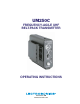
UM250C FREQUENCY-AGILE UHF BELT-PACK TRANSMITTER OPERATING INSTRUCTIONS Rio Rancho, NM www.lectrosonics.
UM250C 2
UHF Belt-Pack Transmitter INTRODUCTION Thank you for selecting the Lectrosonics UM250C frequency agile, belt-pack transmitter. The UM250C combines over 80 years of engineering experience with the very latest components, in a design that addresses the most demanding professional applications. The design of the UM250C was the direct result of numerous conversations with users, staging and touring companies and dealers across the US.
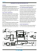
UM250C GENERAL TECHNICAL DESCRIPTION GENERAL The 200 series uses 75kHz wide deviation for an ex tremely high signal to noise ratio. The transmitter circuits are all regulated to allow full output power from the beginning (9 Volts) to the end (7 Volts) of battery life. The input amplifier uses a Motorola 33078 op amp for ultra low noise operation. It is gain controlled with a wide range input compressor which cleanly limits input signal peaks over 30dB above full modulation.
UHF Belt-Pack Transmitter signal following the microphone preamp, just after the compandor, to control the audio output muting of the receiver. The pilot tone is filtered out of the audio signal immediately after the detector in the receiver so that it does not influence the compandor or various gain stages.
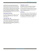
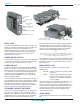
UM250C Power ON/O CONTROLS AND FUNCTIONS Input Jack Frequency Select Switches Power LED Power ON/OFF Switch AUDIO LEVEL Control Modulation LEDs ANTENNA Connector Low Frequency Roll-Off Adjustment (Under Cap) INPUT JACK The input on the UM250C accommodates virtually every lavalier, hand-held or shotgun microphone available. Line level signals can also be accommodated. Use a Switchcraft TA5F connector on the cord.
UHF Belt-Pack Transmitter OFF Switch ANTENNA The flexible wire antenna supplied with the transmitter is cut to 1/4 wavelength of the center of the frequency block (the frequency range) of the transmitter. It is removable via an SMA connector. The SMA connector is a 50 Ohm RF port which can also be connected directly to test equipment. Replacement antennas are available in pre cut lengths for specific frequency blocks, or as a kit with instructions to cut the antenna for any frequency block.
UM250C OPERATING INSTRUCTIONS 1) Install a fresh battery according to the instructions above. lights as you speak. Gradually, turn the gain up until one LED lights, then the other. 2) Insert the microphone plug into the input jack, aligning the pins; be sure that the connector locks in. The -20 LED lights when the audio level is about 12dB below full modulation. The “0” LED lights when the limiter begins to operate.
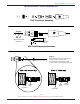
UHF Belt-Pack Transmitter MICROPHONE CORD TERMINATION TA5F Connector Assembly 1 4 5 2 3 VIEW FROM SOLDER SIDE OF PINS 0.15" 0.3" Heatshrink Tubing Mic Cord Stripping Instructions Caution! Do not allow the shield wire to touch any metal part of the connector shell. The shield wire is the antenna on VHF models and poor operating range will result.
UM250C 5-PIN INPUT JACK WIRING The wiring diagrams shown on the next page represent the basic wiring necessary for the most common types of microphones and other audio inputs. Some microphones may require extra jumpers or a slight variation on the dia grams shown. Caution When wiring the connector, do not use the connector body for any electrical connections. A common mistake is to use the connector body as an audio ground.
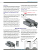
UHF Belt-Pack Transmitter The best RF protection is accomplished by installing RF bypass capacitors at the mic capsule. If this is not pos sible, or if you are still having problems, capacitors can be installed on the mic wires inside the TA5F connector hous ing. 2 WIRE MIC 3 WIRE MIC Preferred locations for bypass capacitors SHIELD SHIELD Install the capacitors as follows: Use 330 pF capacitors. Capacitors are available from Lectrosonics. Please specify the part number for the desired lead style.
UM250C TROUBLESHOOTING Before going through the following chart, be sure that you have a good battery in the transmitter. It is important that you follow these steps in the sequence listed. SYMPTOM POSSIBLE CAUSE TRANSMITTER BATTERY LED OFF 1. Battery is inserted backwards. 2. Battery is dead. NO TRANSMITTER MODULATION LEDs 1. Gain control turned all the way down. 2. Battery is in backwards. Check power LED. 3. Mic capsule is damaged or malfunctioning. 4. Mic cable damaged or mis-wired.
UHF Belt-Pack Transmitter SERVICE AND REPAIR If your system malfunctions, you should attempt to correct or isolate the trouble before concluding that the equipment needs repair. Make sure you have followed the setup procedure and operating instructions.
UM250C SPECIFICATIONS AND FEATURES Operating frequencies: 537.600 to 607.900 MHz 614.100 to 767.900 MHz Frequency selection: 256 frequencies in 100kHz steps RF Power output: 250 mW Pilot tone: 32.764 kHz (± 2Hz); 5kHz deviation Frequency stability: ± 0.002% Deviation: ± 75 kHz (max) Spurious radiation: 90 dB below carrier at frequencies less than 1GHz Equivalent input noise: -126 dBV Input level: Nominal 2 mV to 300 mV, before limiting. Mic input greater than 2V, with limiting.
UHF Belt-Pack Transmitter Rio Rancho, NM – USA 15
LIMITED ONE YEAR WARRANTY LIMITED ONE YEAR WARRANTY The equipment is warranted for one year from date of purchase against defects in materials or workmanship provided it was purchased from an authorized dealer. This warranty does not cover equipment which has been abused or damaged by careless handling or shipping. This warranty does not apply to used or demonstrator equipment. Should any defect develop, Lectrosonics, Inc.