UM200 FREQUENCY-AGILE, BELT-PACK TRANSMITTER OPERATING INSTRUCTIONS and trouble-shooting guide LECTROSONICS, INC.
INTRODUCTION Thank you for selecting the Lectrosonics UM200 frequency agile, belt-pack transmitter. The UM200 combines over 80 years of engineering experience with the very latest components, in a design that addresses the most demanding professional applications. The design of the UM200 was the direct result of numerous conversations with users, staging and touring companies and dealers across the US.
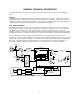
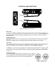
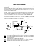
GENERAL TECHNICAL DESCRIPTION The UM200 transmitters are comprised of a number of functional sub-systems as shown in the block diagram below. GENERAL The 200 system uses 75kHz wide deviation for an extremely high signal to noise ratio. The transmitter circuits are all regulated to allow full output power from the beginning (9 Volts) to the end (6 Volts) of battery life. The input amplifier uses a Motorola 33178 op amp for ultra low noise operation.
NO PRE-EMPHASIS/DE-EMPHASIS The signal to noise ratio of the 200 system is high enough to preclude the need for conventional pre-emphasis (HF boost) in the transmitter and de-emphasis (HF roll off) in the receiver.
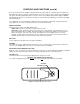
CONTROLS AND FUNCTIONS E D C B A F 0 1 2 3 4 5 9 8 7 6 E D C B A F 0 1 FREQUENCY 2 3 4 5 9 8 7 1.6M 100K 6 LECTROSONICS UM200 FREQUENCY ADJUST ON MUTE OFF LEVEL LIMIT LF ROLL-OFF ADJUST MIC LEVEL 30Hz 150Hz Figure 2 - UM200 Controls and Functions INPUT JACK The input on the UM200 accommodates virtually every lavalier, hand-held or shotgun microphone available. Line level signals can also be accommodated. Use a Switchcraft TA5F connector on the cord.
CONTROLS AND FUNCTIONS (cont’d) Since the internal circuits are all tightly regulated and the RF output stage has a separate discrete regulator, the transmitter will continue to operate to a battery voltage of 6.5 Volts. From 6.5 Volts to 6 Volts, the transmitter will still operate, but with degraded performance.
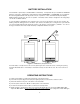
BATTERY INSTALLATION The transmitter is powered by a standard alkaline 9 Volt battery. It is important that you use ONLY an ALKALINE battery for longest life. Standard zinc-carbon batteries marked "heavy-duty" or "long-lasting" are not adequate. Ni-cad rechargeable batteries will only provide 2 hours of operation, or less, and will run down quite abruptly. Alkaline batteries provide over 4.5 hours of operation.
as you speak. Gradually, turn the gain up until one LED lights, then the other. The LEVEL LED lights when the audio level is about 12dB below full modulation. The LIMIT LED lights when the limiter begins to operate. There is over 30dB of limiting range without overload above the LIMIT LED, so it is normal that the LIMIT LED light up 5% to 10% of the time during use. 7) Once the gain has been adjusted, the transmitter audio can be turned on to make sound system level adjustments.
UM200 INPUT JACK WIRING The wiring diagrams shown on the separate sheet represent the basic wiring necessary for the most common types of microphones and other audio inputs. Some microphones may require extra jumpers or a slight variation on the diagrams shown. It’s virtually impossible to keep completely up to date on changes that other manufacturers make to their products. It is possible that you may encounter a microphone that differs from these instructions.
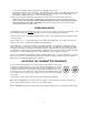
TROUBLESHOOTING Before going through the following chart, be sure that you have a good battery in the transmitter. It is important that you follow these steps in the sequence listed. SYMPTOM POSSIBLE CAUSE TRANSMITTER BATTERY LED OFF 1) Battery is inserted backwards. 2) Battery is dead.
SPECIFICATIONS AND FEATURES Operating frequencies: 470 to 608 MHz, 614 to 806 MHz Frequency selection: 256 frequencies in 100kHz steps RF Power output: 100 mW (nominal) Pilot tone: 32.764 kHz (± 2Hz); 5kHz deviation Frequency stability: ± 0.002% Deviation: ± 75 kHz (max) Spurious radiation: 90 dB below carrier Equivalent input noise: -126 dBV Input level: Nominal 2 mV to 300 mV, before limiting. Greater than 50 Volts maximum, with limiting.
SERVICE AND REPAIR If your system malfunctions, you should attempt to correct or isolate the trouble before concluding that the equipment needs repair. Make sure you have followed the setup procedure and operating instructions. Check out the inter-connecting cords and then go through the TROUBLESHOOTING section in the manual. We strongly recommend that you do not try to repair the equipment yourself and do not have the local repair shop attempt anything other than the simplest repair.
LIMITED ONE YEAR WARRANTY The equipment is warranted for one year from date of purchase against defects in materials or workmanship provided it was purchased from an authorized dealer. This warranty does not cover equipment which has been abused or damaged by careless handling or shipping. This warranty does not apply to used or demonstrator equipment. Should any defect develop, we will, at our option, repair or replace any defective parts without charge for either parts or labor.