UM195B UHF BELT-PACK TRANSMITTER OPERATING INSTRUCTIONS and trouble-shooting guide LECTROSONICS, INC. Rio Rancho, NM www.lectrosonics.
UM195B INTRODUCTION Thank you for selecting the Lectrosonics UM195B belt-pack transmitter. The UM195B combines over 80 years of engineering experience with the very latest components, in a design that addresses the most demanding professional applica tions. The design of the UM195B was the direct result of numerous conversations with users and dealers across the US.
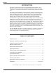
UHF Belt-Pack Transmitter GENERAL TECHNICAL DESCRIPTION The UM195B transmitter is comprised of a number of functional sub-systems as shown in the block diagram below. The 195 system uses +/-75kHz deviation. The transmitter circuits are all regulated to allow full output power from the beginning (9 Volts) to the end (7 Volts) of battery life. The oscillator crystal is shock mounted to provide ruggedness. The input amplifier uses a Motorola 33078 op amp for ultra low noise operation.
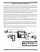
UM195B CONTROLS AND FUNCTIONS LECTROSONICS UM195B OFF ON 75 Hz 35 150 FCC ID: DBZUM195 Lectrosonics, Inc. Made in U.S.A. SN: XXXX LF ROLL OFF AUDIO LEVEL 0 –20 LF ROLL-OFF Adjustment ANTENNA INPUT JACK The 5-pin input jack accommodates virtually every lavalier, hand-held or shotgun microphone available. Use a Switchcraft TA5F connector on the cord. See the separate sheet titled “Transmitter 5-Pin Input Jack Wiring” regarding the correct connections for various microphones, and other sources.
UHF Belt-Pack Transmitter MODULATION LEDS Indicate the proper setting of the MIC LEVEL control. LEVEL LED -- Flickers or glows when sufficient audio is present. LIMIT LED -- Lights up when the input level is high enough to cause limiting. The input limiter has a very high overload threshold (over 30 dB). Generally speaking, some limiting is desirable in normal operation to improve the signal to noise ratio of the system. The limiting action is not audible and does not create distortion.
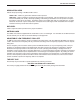
UM195B BATTERY INSTALLATION The transmitter is powered by a 9 Volt alkaline or lithium battery. It is important that you use ONLY an ALKALINE or LITHIUM battery for longest life. Standard zinc-carbon batteries marked “heavy-duty” or “long-lasting” are not ad equate. Ni-cad rechargeable batteries will only provide 2 hours of operation, or less, and will run down quite abruptly. The battery status circuitry is designed for the voltage drop over the life of alkaline batteries.
UHF Belt-Pack Transmitter OPERATING INSTRUCTIONS 1) Install a fresh battery according to the instructions on the previous page. 2) Insert the microphone plug into the input jack, aligning the pins; be sure that the connector locks in. 3) Attach the antenna to the jack on the control panel of the unit. Be sure it is screwed in securely. 3) Turn the power switch to the “ON.” 4) Position the microphone in the location you will use in actual operation.
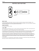
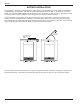
UM195B MICROPHONE CORD TERMINATION TA5F Connector Assembly 1 4 5 2 3 VIEW FROM SOLDER SIDE OF PINS 0.15" 0.3" Heatshrink Tubing Mic Cord Stripping Instructions Caution! Do not allow the shield wire to touch any metal part of the connector shell. The shield wire is the antenna on VHF models and poor operating range will result.
UHF Belt-Pack Transmitter 5-PIN INPUT JACK WIRING The wiring diagrams shown on the separate sheet represent the basic wiring necessary for the most common types of microphones and other audio inputs. Some microphones may require extra jumpers or a slight variation on the dia grams shown. Caution - When wiring the connector, do not use the connector body for any electrical connections. A common mistake is to use the connector body as an audio ground.
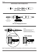
UM195B RF BYPASSING 2 WIRE MIC Some mics require RF protection to keep the radio signal from affecting the capsule, even though the transmitter input circuitry is already RF bypassed (see schematic diagram). 3 WIRE MIC Preferred locations for bypass capacitors SHIELD SHIELD If the mic is wired as directed, and you are having difficulty with squealing, high noise, or poor frequency response; RF is likely to be the cause.
UHF Belt-Pack Transmitter TROUBLESHOOTING Before going through the following chart, be sure that you have a good battery in the transmitter. It is important that you follow these steps in the sequence listed. SYMPTOM POSSIBLE CAUSE TRANSMITTER BATTERY LED OFF 1) Battery is inserted backwards. 2) Battery is dead. NO TRANSMITTER MODULATION LEDs 1) Gain control turned all the way down. 2) Battery is in backwards. Check power LED. 3) Mic capsule is damaged or malfunctioning.
UM195B SPECIFICATIONS AND FEATURES Operating frequencies: 470 to 608 MHz RF Power output: 70 mW (nominal) Frequency stability: ±0.002% Deviation: ±75 kHz (max) Preemphasis: None Spurious radiation: 50 dB below carrier Equivalent input noise: -126 dBV Input level: Nominal 2 mV to 300 mV, before limiting. Greater than 50 Volts maximum, with limiting.
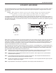
UHF Belt-Pack Transmitter SERVICE AND REPAIR If your system malfunctions, you should attempt to correct or isolate the trouble before concluding that the equipment needs repair. Make sure you have followed the setup procedure and operating instructions.
LIMITEDONE ONE YEAR LIMITED YEARWARRANTY WARRANTY The equipment is warranted for one year from date of purchase against defects in materials or workmanship provided it was purchased from an authorized dealer. This warranty does not cover equipment which has been abused or damaged by careless handling or shipping. This warranty does not apply to used or demonstrator equipment. Should any defect develop, Lectrosonics, Inc.