UM110 UHF MULTI-FREQUENCY BELT-PACK TRANSMITTER EURO MODEL OPERATING INSTRUCTIONS and trouble-shooting guide LECTROSONICS, INC. www.lectrosonics.
TABLE OF CONTENTS INTRODUCTION .................................................................................................. 3 GENERAL TECHNICAL DESCRIPTION ............................................................ 4 CONTROLS AND FUNCTIONS .......................................................................... 6 BATTERY INSTALLATION ................................................................................... 8 OPERATING INSTRUCTIONS ...................................................
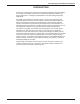
Multi-frequency UHF Belt-Pack Transmitter INTRODUCTION Thank you for selecting the Lectrosonics UM110 multi-frequency, belt-pack transmit ter. The UM110 combines over 80 years of engineering experience with the very latest components, in a design that addresses the most demanding professional applications. The design of the UM110 was the direct result of numerous conversations with users and dealers across the US.
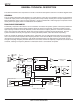
GENERAL TECHNICAL DESCRIPTION The UM110 transmitters are comprised of a number of functional sub-systems as shown in the block diagram below. GENERAL The 110 system uses 20 kHz wide deviation for a high signal to noise ratio. The transmitter circuits are all regulated to allow full output power from the beginning (9 Volts) to the end (6.5 Volts) of battery life. The input amplifier uses a Motorola 33078 op amp for ultra low noise operation.
Multi-frequency UHF Belt-Pack Transmitter PRE-EMPHASIS/DE-EMPHASIS The signal to noise ratio of the 110 system is extended by using pre-emphasis (HF boost) in the transmitter and deemphasis (HF roll off) in the receiver.
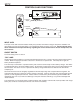
CONTROLS AND FUNCTIONS FREQUENCY COURSE FINE E D C B A F 0 1 2 3 4 5 9 8 7 6 E D C B A F 0 1 2 3 4 5 9 8 7 6 LECTROSONICS UM110 Frequency Adjust OFF ON AUDIO LEVEL 0 LF Roll-Off Adjust –20 ANTENNA 75 Hz 35 150 LF ROLL OFF INPUT JACK The input on the UM110 accommodates virtually every lavalier, hand-held or shotgun microphone available. Line level signals can also be accommodated. Use a Switchcraft TA5F connector on the cord.
Multi-frequency UHF Belt-Pack Transmitter FREQUENCY ADJUST These two rotary switches adjust the center frequency of the carrier. The left switch is a COARSE adjustment and the right switch is the FINE adjustment. Each transmitter is factory aligned at the center of its operating range. The default position of the frequency select switches is in the center of the transmitter’s range. Refer to the chart of settings provided with the unit.
BATTERY INSTALLATION The transmitter is powered by a standard alkaline or lithium 9 Volt battery. It is important that you use ONLY an ALKALINE or LITHIUM battery for longest life. Standard zinc-carbon batteries marked “heavy-duty” or “long lasting” are not adequate. Ni-cad rechargeable batteries will only provide 1.5 hours of operation, or less, and will run down quite abruptly. Alkaline batteries provide over 4.5 hours of operation. Lithium batteries can be used to provide up to 14 hours.
Multi-frequency UHF Belt-Pack Transmitter OPERATING INSTRUCTIONS 1) Install a fresh battery according to the instructions above. 2) Insert the microphone plug into the input jack, aligning the pins; be sure that the connector locks in. 3) Mute the sound system. 4) Turn the transmitter power switch to the “ON” position. 5) Position the microphone in the location you will use in actual operation. 6) While speaking or singing at the same voice level that will actually be used, observe the MODULATION LEDs.
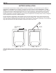
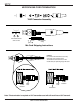
MICROPHONE CORD TERMINATION TA5F Connector Assembly 1 4 5 2 3 VIEW FROM SOLDER SIDE OF PINS 0.15" 0.3" Heatshrink Tubing Mic Cord Stripping Instructions Caution! Do not allow the shield wire to touch any metal part of the connector shell. The shield wire is the antenna on VHF models and poor operating range will result.
Multi-frequency UHF Belt-Pack Transmitter ters. 5-PIN INPUT JACK WIRING The wiring diagrams shown on the next page represent the basic wiring necessary for the most common types of microphones and other audio inputs. Some microphones may require extra jumpers or a slight variation on the diagrams shown. Caution - When wiring the connector, do not use the connector body for any electrical connections. A common mistake is to use the connector body as an audio ground.
PIN 5 High impedance, line level input for tape decks, mixer outputs, musical instruments, etc. 2 WIRE MIC 3 WIRE MIC Preferred locations for bypass capacitors RF BYPASSING SHIELD Some mics require RF protection to keep the radio signal from affecting the capsule, even though the transmitter input circuitry is already RF bypassed (see schematic diagram).
Multi-frequency UHF Belt-Pack Transmitter TROUBLESHOOTING Before going through the following chart, be sure that you have a good battery in the transmitter. It is important that you follow these steps in the sequence listed. SYMPTOM POSSIBLE CAUSE TRANSMITTER BATTERY LED OFF 1) Battery is inserted backwards. 2) Battery is dead. NO TRANSMITTER MODULATION LEDs 1) Gain control turned all the way down. 2) Transmitter battery is dead. Check power LED. 3) Mic capsule is damaged or malfunctioning.
SPECIFICATIONS AND FEATURES Operating frequencies: 525.000 to 862.000 MHz Frequency selection: Up to 256 frequencies Channel spacing: 100kHz (25kHz programmable) RF Power output: 50 mW (nominal) Frequency stability: +/- 0.001% Deviation: +/- 20 kHz typ., +/- 50kHz max Spurious radiation: 90 dB below carrier Equivalent input noise: -126 dBV Input level: Nominal 2 mV to 300 mV, before limiting. Greater than 3V maximum, with limiting.
Multi-frequency UHF Belt-Pack Transmitter This page intentionally blank.
LIMITEDONE ONE YEAR WARRANTY LIMITED YEAR WARRANTY The equipment is warranted for one year from date of purchase against defects in materials or workmanship provided it was purchased from an authorized dealer. This warranty does not cover equipment which has been abused or damaged by careless handling or shipping. This warranty does not apply to used or demonstrator equipment. Should any defect develop, Lectrosonics, Inc.