INSTRUCTION MANUAL UH400A UH400TM Frequency Agile Plug-On UHF Transmitter Featuring Digital Hybrid Wireless™ Technology U.S. Patent 7,225,135 Fill in for your records: Serial Number: Purchase Date: Rio Rancho, NM, USA www.lectrosonics.
UH400A/UH400TM This plug-on transmitter is an advanced design that has evolved since the first models appeared in the late 1980’s serving ENG applications at television stations across the USA. In the mid-1990’s, the first UHF versions became available and the use of plug-on transmitters in motion picture production increased significantly. The current UH400A model has evolved to include every improvement and feature developed since the first model was introduced.
Frequency Agile Plug-On UHF Transmitter Table of Contents General Technical Description...............................................................................................................................................................4 Introduction............................................................................................................................................................................................4 Digital Hybrid Technology ...................................
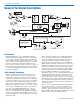
UH400A/UH400TM General Technical Description UH400A Block Diagram Introduction Digital Hybrid Wireless™ is a wideband design with ±75 kHz deviation produding an excellent audio signal to noise ratio and wide dynamic range. The switching power supplies provide constant voltages to the transmitter circuits from the beginning (9.3 Volts) to the end (5.5 Volts) of battery life. The input amplifier uses an ultra low noise op amp for quiet operation.
Frequency Agile Plug-On UHF Transmitter Input Limiter Wide-Band Deviation The Digital Hybrid Wireless transmitters employ a digitally-controlled analog audio limiter just before the analog-to-digital converter. The limiter has a range of more than 30 dB for excellent overload protection. A dual release envelope makes the limiter acoustically transparent while maintaining low distortion.
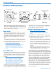
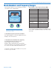
UH400A/UH400TM Controls and Functions MODULATION LEDS -20 -10 INPUT JACK POWER ON/OFF LED FREQUENCY SWITCHES (BEHIND DOOR) POWER SWITCH E D C B A F 0 1 9 8 7 2 6 3 4 5 1.6MHz NO PHTM PHTM INPUT JACK LEVEL 48 The PHTM (center) position of the power switch turns on the phantom power value selected by the Phantom Power Voltage Select switch, while the NO PHTM (fully on) position disables phantom power.
Frequency Agile Plug-On UHF Transmitter The transmitter can supply 4 mA at 42 Volts, 8 mA at 15 Volts, and 8 mA at 5 Volts. The 42 Volts setting actually supplies the same voltage to a 48 Volt microphone as the DIN standard arrangement due to a dynamic biasing scheme that does not have as much voltage drop as the DIN standard. The 48 Volt DIN standard arrangement protects against shorts and high fault current with high resistance in the power supply feeds to pins 2 and 3.
UH400A/UH400TM Compatibility Mode Indicators At power up, all three LEDS will blink together red, then green, followed by the -20 and -10 dB LEVEL LEDs blinking together to indicate the operating mode.
Frequency Agile Plug-On UHF Transmitter Block Numbers and Freqeuncy Ranges The transmitter will tune to any of 256 different frequencies within a factory assigned block. E D C B A F 0 1 9 8 7 2 6 3 4 5 E D C B A F 0 1 9 8 7 2 6 3 4 5 Two 16- position switches adjust the operating frequency in 100 kHz steps yielding the 256 in a block (16 x 16 = 256). Block Numbers and Frequency Ranges (MHz): Block 470 470.100 - 495.600 Block 19 486.400 - 511.900 Block 20 512.000 - 537.500 Block 21 537.
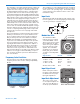
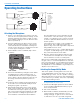
UH400A/UH400TM Operating Instructions TO ATTACH TO REMOVE Hold the transmitter case with the microphone pointed upward. Rotate the collar in the direction shown. Press firmly, listen for click. Depress collar fully. Click! Pull on mic to ensure it is locked. Attaching the Microphone 1. Set the correct phantom power voltage for the mic.
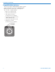
Frequency Agile Plug-On UHF Transmitter 4. Set the Power Switch to NO PHTM briefly – just a couple of seconds for the front panel LED’s to light up, then turn the unit off. 5. Change the Frequency Select switches to one of the following settings: MODE SWITCH SETTINGS 100 Series 1,1 200 Series 2,2 Mode 3* 3,3 400 Series (Digital Hybrid) 4,4 IFB Mode 5,5 Mode 6* 6,6 Battery Replacement The transmitter is powered by a standard 9 volt battery. Alkaline, Li Polymer rechargeable and lithium types can be used.
UH400A/UH400TM Using the PolarityReversing Barrel Adapter The UH400TM transmitter comes with a polarity-reversing XLR barrel adapter for use with Earthworks M30 measurement microphones. Simply connect the adapter between the transmitter and microphone. Part #21750 Earthworks M30 Accessories PHTRAN2 Cordura Pouch with belt clip and velcro flap. (Included with TX) MC5AX (optional) TA5 to XLR adapter for connecting a lavaliere microphone to the UH400.
Frequency Agile Plug-On UHF Transmitter Troubleshooting Before going through the following chart, be sure that you have a good battery in the transmitter. It is important that you follow these steps in the sequence listed. Symptom Possible Cause Transmitter Battery LED Off 1. Battery is inserted backwards. 2. Battery is dead. No Transmitter Modulation LEDs 1. 2. 3. 4. 5. Receiver RF Lamp Off 1. 2. 3. 4. 5. Gain control turned all the way down. Battery is in backwards. Check power LED.
UH400A/UH400TM Specifications and Features Operating frequencies: Frequency selection: RF Power output: Pilot tone: Frequency stability: Deviation: Spurious radiation: Equivalent input noise: Input level: Input impedance: Phantom power: Input limiter: Gain control range: Modulation indicators: Low frequency roll-off: Controls: Audio Frequency Response: Signal to Noise Ratio (dB): Note: The dual envelope “soft” limiter provides exceptionally good handling of transients using variable attack and rele
Frequency Agile Plug-On UHF Transmitter Service and Repair If your system malfunctions, you should attempt to correct or isolate the trouble before concluding that the equipment needs repair. Make sure you have followed the setup procedure and operating instructions. Check the interconnecting cables and then go through the Troubleshooting section in this manual.
LIMITED ONE YEAR WARRANTY The equipment is warranted for one year from date of purchase against defects in materials or workmanship provided it was purchased from an authorized dealer. This warranty does not cover equipment which has been abused or damaged by careless handling or shipping. This warranty does not apply to used or demonstrator equipment. Should any defect develop, Lectrosonics, Inc. will, at our option, repair or replace any defective parts without charge for either parts or labor.