UDR200B RATIO DIVERSITY UHF RECEIVER OPERATING INSTRUCTIONS and trouble-shooting guide LECTROSONICS, INC.
Wireless Diversity Receiver TABLE OF CONTENTS GENERAL TECHNICAL DESCRIPTION ............................................................. 4 FRONT PANEL CONTROLS AND FUNCTIONS................................................. 7 REAR PANEL CONTROLS AND FUNCTIONS ................................................... 8 INSTALLATION AND OPERATING INSTRUCTIONS ......................................... 9 USING THE LED INFORMATION DISPLAY ......................................................
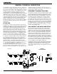
GENERAL TECHNICAL DESCRIPTION The UDR200B consists of two high performance, dual-conver sion receivers operating simultaneously. The audio outputs of the receivers are blended in a ratio controlled by the compara tive RF levels in the receivers. The multistage RF front end is a unique design that is tuned by a microprocessor to the selected frequency.
Wireless Diversity Receiver DOUBLE BALANCED DIODE MIXERS In all wireless receivers, a mixer is used to convert the carrier frequency to the IF frequency where most of the filtering and gain in the receiver takes place. After doing all the right things in the front end, it would be a shame to waste the performance with a second rate mixer. In other designs that is exactly what happens since mediocre mixers cause more intermodulation problems than mediocre front ends.
the audio frequency range unless the RF level drops to very low levels. At weak RF levels, the filter operates in the TRI MODE state until the RF level rises back to acceptable levels. This has the desirable effect of softening dropouts. We recom mend using the RF ONLY setting when it is desirable to pick up high frequency background noise, such as for a location shot for a movie. This might be machinery noise, compressed air, etc.
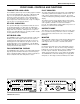
Wireless Diversity Receiver FRONT PANEL CONTROLS AND FUNCTIONS TRANSMITTER AUDIO LEVEL PILOT INDICATOR The modulation (audio level) of the incoming signal is indicated by a fast responding LED strip. The strip is calibrated in 6dB steps over an expanded scale (54dB) which provides an extremely accurate visual “picture” of the signal dynamics, even at a distance away from the receiver.
REAR PANEL CONTROLS AND FUNCTIONS AUDIO OUTPUT ANTENNA JACKS A calibrated control on the rear panel adjusts the output level in 5 dB steps, referenced in dBu. This control knob adjusts the absolute output level at the XLR connector. The AUDIO OUT PUT level control is located after the output transformer. This allows the signal to noise ratio to remain constant regardless of the setting of the control. As the audio level is reduced, the noise is also reduced maintaining the same ratio.
Wireless Diversity Receiver INSTALLATION AND OPERATING INSTRUCTIONS 1) Locate a suitable operating location where the receiver will not be subjected to extreme temperature variations and possible bumps and drops. Try to route all wiring so it will not cross walkways or isles. 6) Turn the unit on with the front panel POWER switch and check to see that the PILOT indicator is blinking indicating that the pilot tone is not being received (be sure the trans mitter is turned off.) 2) Connect the power.
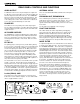
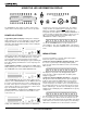
USING THE LED INFORMATION DISPLAY A 1uV 2 5 10 25 50 100 250 500 1mV RF LEVEL 6 6 8 . 1 0 0 1uV 2 5 10 8 . 7 V RF LEVEL 25 50 100 250 500 1mV OPTI BLEND -48 -42 -36 -30 -24 -18 -12 -6 0 LIM TX AUDIO LEVEL dB FREQ SELECT 1 9 DIVERSITY OPTI BLEND A B B MODE MONITOR POWER MENU The UDR200B has three power up options and four menu options which control all aspects of the receiver’s operation.
Wireless Diversity Receiver quency, and will stop flashing when a valid Pilot Tone is de tected. Use the UP and DOWN buttons on the receiver front panel to select from frequencies stored in the currently active group. The UP and DOWN buttons will repeat if pushed and held. The display will blink to indicate that the highest or lowest frequency in the current group has been reached. To select frequencies in 100kHz steps, press the MENU button plus the UP or DOWN buttons.
LecNetTM COMPUTER INTERFACE Lectrosonics’ LecNet system is a unique implementation of standard RS-232 serial communications. Since it is compat ible with RS-232 serial ports found on all PCs, no extra inter face cards are necessary to add computer control to your LecNet equipment. The figure below shows a representation of a LecNet setup.
Wireless Diversity Receiver LecNetTM COMPUTER INTERFACE MICROPROCESSOR CONTROL For multi-channel systems, each UDR200B receiver is assigned a unique serial address from the front panel of the receiver. When the LecNetTM Master Pro software is then launched, a role call is initially taken to identify all devices that are connected. An internal microprocessor controls the frequency settings and display, and provides a user friendly interface for setup and operation.
FREQUENCY BLOCKS AND RANGES The table below lists the factory designated frequency ranges available for the UDR200B receiver. For convenience, the table includes information about the UM200B belt-pack trans mitter antennas as well. this case, 685.500 MHz falls within block 26. Each UDR200B receiver is built to cover a pre-selected range of frequencies (a “block”) as shown below. The receiver will tune to any of 256 different frequencies within this factory assigned block.
Wireless Diversity Receiver ANTENNA USE AND PLACEMENT like “hiss” or a “swishing” sound. Moving the transmitter even a few inches will change the sound of the hum or hiss, or elimi nate it. A drop-out situation may be either better or worse as the crowd fills and/or leaves the room, or when the transmitter or receiver is operated in a different location.
TROUBLESHOOTING POWER SUPPLY AND FUSE Display not lit or dimly lit • AC power cord disconnected. • External power supply disconnected or inadequate. • Main power supply defective. • The External DC power input is protected by an auto-reset polyfuse. Disconnect power and wait about 10 seconds for the fuse to reset. Receiver won’t turn off • This is normal when the unit is being operated from exter nal DC power. PILOT TONE SQUELCH The pilot indicator is the transmitter switch settings display.
Wireless Diversity Receiver SERVICE AND REPAIR If your system malfunctions, you should attempt to correct or isolate the trouble before con cluding that the equipment needs repair. Make sure you have followed the setup procedure and operating instructions.
SPECIFICATIONS AND FEATURES Operating Frequencies: 537.600 to 588.700 MHz; 614.400 to 793.500 MHz Frequency Adjustment Range: Receiver Type: Frequency Stability: Front end selectivity: 25.5 MHz Dual conversion, superheterodyne, 71MHz and 455kHz ±0.002 % >22 dB at ±4 MHz Sensitivity 20 dB Sinad: 60 dB Quieting: Squelch quieting: 0.707 uV (-110 dBm), A weighted 1.
Wireless Diversity Receiver LecNet SOFTWARE PROTOCOL Note: This section is for developement of custom control applications and is not necessary for general operation of the receiver and the LecNet control software provided by the factory. The UDR200B uses a modification of the typical one-to-one connection between two RS-232 compatible devices. The UDR200B has both an RS-232 transmitter and receiver sec tion.
LecNet SOFTWARE PROTOCOL Two Byte Format for Data sent from Host When the host must send data to a LecNet device whose value exceeds 127, the data must be broken into two succes sive bytes. This avoids having other LecNet devices interpret the host data as an address, since the address space is 128 254. If the host must send a data value that exceeds 127, two bytes are output such that the first byte is the lower 7 bits of the 8 bit value.
Wireless Diversity Receiver Output Group Frequency and Name - Outputs specific name/frequency entries stored in non-volatile memory. Each of the entries, up to a total of 16 in each group, consists of 14 bytes. The first byte is the frequency, and the next thirteen are the name associated with that frequency. Host sends command - 18 Host sends data bytes: Byte 1: Group number to down load to, 1 - 4. Byte 2: Group entry number, 1 - 16.
LIMITED ONE YEAR WARRANTY The equipment is warranted for one year from date of purchase against defects in materials or workmanship provided it was purchased from an authorized dealer. This warranty does not cover equipment which has been abused or damaged by careless handling or shipping. This warranty does not apply to used or demonstrator equipment. Should any defect develop, we will, at our option, repair or replace any defective parts without charge for either parts or labor.