Wireless Diversity Receiver UDR195 RA TIO DIVERSITY RECEIVER RATIO OPERA TING INSTR UCTIONS OPERATING INSTRUCTIONS and trouble-shooting guide LECTROSONICS, INC.
Table of Contents INTRODUCTION TO THE 195 SYSTEM ......................................... 4 MODULAR DESIGN ............................................................................................... 4 T195 TRANSMITTER ............................................................................................. 5 M195 TRANSMITTER ............................................................................................ 5 DUAL-BAND COMPANDOR .............................................................
Wireless Diversity Receiver ANTENNA USE AND PLACEMENT .............................................. 12 INSTALLATION AND OPERATING INSTRUCTIONS ................... 13 TROUBLESHOOTING ................................................................... 14 POWER SUPPLY AND FUSE .............................................................................. 14 PILOT TONE SQUELCH ...................................................................................... 14 ANTENNAS AND RF SIGNAL STRENGTH ............
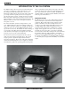
INTRODUCTION TO THE 195 SYSTEM The DR195 employs the most advanced circuit and mechani cal design ever applied to a wireless microphone receiver. Two independent, ultra-high performance receivers are blended in a highly effective ratio diversity design. The audio processing is the finest quality system ever developed for wireless microphone systems. A unique design of a modular RF section allows quick frequency changes, yet preserves the high performance of an advanced fixed frequency design.
Wireless Diversity Receiver T195 TRANSMITTER 75KHz DEVIATION The T195 hand-held transmitter design was the result of considerable research. The RF and audio performance of the transmitter was considered first, followed by an analysis of the typical user’s needs and the practicality of various design possibilities. The basic circuitry had to accommodate any frequency in the VHF or UHF spectrums. The mechanical design had to provide a comfortable “feel,” yet be rugged, foolproof and easy to operate.
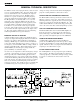
GENERAL TECHNICAL DESCRIPTION The DR195 consists of two high performance, dual-conversion receivers operating simultaneously. The audio outputs of the receivers are blended in a ratio controlled by the compared signal to noise ratios of the receivers. The RF section is mounted on a separate circuit board, permitting frequency changes by simply interchanging the RF section assembly.
Wireless Diversity Receiver DIGITAL PULSE COUNTING DETECTOR The DR195 receiver uses an advanced digital pulse detector to demodulate the FM signal, rather than a conventional quadra ture detector. The most common problem with quadrature detectors is thermal drift, particularly those that operate at higher frequencies like 10.7 MHz. The DR195 design presents an elegantly simple, yet highly effective solution to this age old problem.
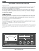
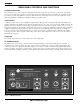
FRONT PANEL CONTROLS AND FUNCTIONS AUDIO OUTPUT LEVEL A high quality VU meter is used to monitor the audio ouput level, providing an accurate indication of the average audio output level. The VU meter sensitivity is adjusted with a rear panel control to compensate for the difference in transient response rise time between the VU meter and the LED strip below the meter. Depending upon the dynamic characteristics of the audio source, it may be necessary to adjust for headroom in the VU meter.
Wireless Diversity Receiver PILOT LED The audio output muting (squelch) function of the DR195 is controlled by a 33kHz tone modulation of the RF carrier. The audio output is muted until this tone is present. As soon as the tone is received, this LED is turned on to indicate the audio output is enabled. The pilot tone function can be defeated by pressing a switch on the rear panel. The PILOT LED, however, operates the same regardless of whether or not the defeat switch is pressed.
REAR PANEL CONTROLS AND FUNCTIONS VU METER HEADROOM Since VU meters are too slow to respond to brief transients in audio signals, they do not indicate “peaks” in the audio signal, however, they do indicate the average levels of the audio signal in the 20dB range below maximum level. A calibrated sensitiv ity control is provided on the DR195 rear panel to allow the VU meter sensitivity to be increased so that it will more closely track the modulation level LED strip with different kinds of program material.
Wireless Diversity Receiver EXTERNAL POWER JACK The DR195 can be powered from external 12 to 18 Volt DC sources via the four pin XLR jack. The jack is non-polarized between pins 1 and 4. Internal relays correct the polarity automatically if reverse polarity is connected. By using relays to correct the power supply polarity, there is no voltage drop, as would occur in a diode bridge circuit. The relays and power supply stage are fully protected by automatic reset poly fuses.
ANTENNA USE AND PLACEMENT There are two remote antenna assemblies included with this receiver. Position the antennas at least three or four feet apart at VHF frequencies and so that they are not within 3 or 4 feet of large metal surfaces. If this is not possible, try to position the antennas so that they are as far away from the metal surface as is practical. It is also good to position the receiver so that there is a direct “line of sight” between the transmitter and the receiver antenna.
Wireless Diversity Receiver INSTALLATION AND OPERATING INSTRUCTIONS 1) If operating the unit from AC power, determine the line voltage to be used and set the Line Voltage Selector on the rear panel to match. The units are shipped with the proper size fuse for use with 120V systems (315mA). If the unit will be used in a 220V environment, change the fuse to a 160mA of the same type.
TROUBLESHOOTING POWER SUPPLY AND FUSE VU meter lamp and LEDs not lit or dimly lit — When the DR195 is powered from an external DC supply, the VU meter lamp stays out and the LEDs are dimmed to conserve battery life. AC power cord disconnected. External power supply disconnected or inadequate. Main power supply fuse blown. For 110 Volt operation: 315 mA, 250 Volt Buss GDC-315 or Littlefuse 218.315 (Lectrosonics part #22090) For 220 Volt operation: 160mA, 250 Volt Buss GDC-160 or Littlefuse 218.
Wireless Diversity Receiver AUDIO SIGNAL QUALITY Poor signal to noise ratio Transmitter gain set too low Noise may not be in wireless system. Mute the audio signal at the transmitter and see if noise remains. If the noise remains, then turn the power off at the transmitter and see if it remains. If the noise is still present, then the problem is not in the transmitter.
SPECIFICATIONS AND FEATURES Receiver Operating Frequencies: 470 to 608 MHz, crystal controlled Receiver Type: Dual conversion, superheterodyne Frequency Stability: ±0.002 % Front end selectivity: >70 dB at ±4 MHz IF Selectivity: >90 dB at ±300 kHz (10.7 IF) IF Frequency: 10.7 MHz (1st IF); 455 kHz (2nd IF) IF bandwidth: 150 kHz at ½ power points Sensitivity 20 dB Sinad: 0.56 uV (-113 dBm), A weighted 60 dB Quieting: 1.
Wireless Diversity Receiver SERVICE AND REPAIR If your system malfunctions, you should attempt to correct or isolate the trouble before concluding that the equipment needs repair. Make sure you have followed the setup procedure and operating instructions.
LIMITED ONE YEAR WARRANTY The equipment is warranted for one year from date of purchase against defects in materials or workmanship provided it was purchased from an authorized dealer. This warranty does not cover equipment which has been abused or damaged by careless handling or shipping. This warranty does not apply to used or demonstrator equipment. Should any defect develop, we will, at our option, repair or replace any defective parts without charge for either parts or labor.