
User Manual


UHF Digital Hybrid Wireless™ Receiver
Rio Rancho, NM
21
Diagnostics
Multi-channel System Checkout
Interference can result from a wide variety of sources
including TV station signals, other wireless equipment
in use nearby, or from intermodulation within a multi-
channel wireless system itself. Regardless of how the
frequencies were coordinated, a final checkout proce-
dure is always a good idea.
Scanning with the RF spectrum analyzer built into the
Venue system will identify external RF signals, but
it does not address the compatibility of the selected
frequencies.
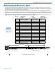
The pre-coordinated frequencies on the chart on the
previous pages address in-system intermodulation,
but obviously cannot take into account RF signals from
external sources that may be present in the location
where the system will be operating.
In some cases, you can run the scanner to find clear TV
channels, then find enough pre-coordinated frequencies
in the tuning groups (Grp a through Grp d) to operate
on the clear TV channels. Even so, it is still a good idea
to go through the check out procedure because you
can encounter interference from other wireless, IFB and
intercom systems when you get to the production or
installation site.
1. Set up the system for testing.
Place antennas in the position in which they will be
used and connect to the receivers. Place transmit-
ters about 3 to 5 feet apart, about 25 to 30 feet from
the receiver antennas. If possible, have all other
equipment on the set, stage or location turned on
as well, especially any mixing or recording equip-
ment that will be used with the wireless system.
2. Set all receivers on clear channels.
Turn on all receivers, but leave the transmitters off.
Observe at the RF signal strength indicator for each
receiver module. If a signal is present, change the
frequency to a clear channel where no signal is
indicated. If a completely clear channel cannot be
found, select the frequency with the lowest RF level
indication. Once all receiver modules are on clear
channels, go to step 3.
3. Turn each transmitter on one at a time.
Start with all transmitters turned off. As you turn on
each one, look at the matching receiver to verify a
strong RF signal is received. Then, look at the other
receivers and see if one of them is also picking up
the signal. Only the matching receiver should indi-
cate a signal. Change frequencies on either system
slightly until all channels pass this test, then check
again to see that all channels are still clear as done
in step 2.
4. Turn each transmitter off one at a time.
With all transmitters and receivers turned on, turn
each transmitter off one at a time, in turn, and look
at the RF level indicator on the matching receiver
module. The RF level should disappear or drop to a
very low level. If it does not, change frequency on
that receiver and transmitter and try it again. When
a clear frequency is found, turn the transmitter on
and move on to the next channel.
IMPORTANT: Any time a frequency is changed on
any of the systems in use, you must start at the
beginning and go through this procedure again for
all systems. With a little practice, you will be able
to do this quickly and save yourself some “multi-
channel grief.”
Pilot Tone Bypass
Some wireless equipment uses a supersonic “pilot tone”
to control the squelch (audio mute) of a receiver module
to keep it silent until a valid signal is received. When a
signal with the correct pilot tone is received, the squelch
opens and audio is delivered to the output. Pilot tone
squelch control also eliminates transients (clicks and
pops) when transmitters are turned on and off. Pilot
tone is supported in the Digital Hybrid compatibility
modes for those systems that use it.
Pilot tone control can be bypassed as a diagnostic tool.
Bypass opens the audio output of the receiver uncondi-
tionally, allowing you to listen to any signals entering the
receiver to help identify their source. Pilot tone bypass
will also allow you to use a transmitter that has a defec-
tive pilot tone circuit.
CAUTION: When pilot tone is bypassed and
the transmitter is turned off, excessive noise
will be present. Turn the audio level down
before bypassing pilot tone.