INSTRUCTION MANUAL UCR401 Compact Wireless Receiver Featuring Digital Hybrid Wireless® Technology U.S. Patent 7,225,135 Fill in for your records: Serial Number: Purchase Date: Rio Rancho, NM, USA www.lectrosonics.
UCR401 2 LECTROSONICS, INC.
UHF Digital Hybrid Wireless® Receiver Digital Hybrid Wireless TM The Lectrosonics Digital Hybrid WirelessTM uses innovative technology to combine the new advantages of digital audio with the advantages of analog RF transmission, thus delivering the superior sound quality of a digital system and the excellent range of an analog system. A proprietary algorithm encodes the digital audio information into an analog format which can be transmitted in a robust manner over an analog FM wireless link.
UCR401 4 LECTROSONICS, INC.
UHF Digital Hybrid Wireless® Receiver Table of Contents General Technical Description...............................................................................................................................................................7 Front Panel Controls and Functions....................................................................................................................................................10 LCD Screen......................................................................
UCR401 6 LECTROSONICS, INC.
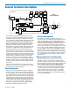
UHF Digital Hybrid Wireless® Receiver General Technical Description RF MODULE SAW FILTER SAW FILTER CERAMIC FILTER XTAL CONTROLLED 3rd OSCILLATOR 244 MHz IF AMP 244 MHz IF AMP 2ND MIXER 10.
UCR401 IF Amplifiers and SAW Filters The first IF stage at 244 MHz employs two state-of-theart SAW (surface acoustic wave) filters. The use of two filters significantly increases the depth of filtering while preserving sharp skirts, constant group delay, and wide bandwidth. Though expensive, this special type of filter allows primary filtering as early as possible, at as high a frequency as possible before high gain is applied to the signal for maximum image rejection.
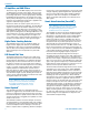
UHF Digital Hybrid Wireless® Receiver Supersonic Noise-Based Dynamic Filter and Squelch In addition to SmartNR, all hybrid receivers are equipped with a supersonic noise-based dynamic filter and squelch system. The incoming audio is monitored for energy above 22 kHz, pilot tone excepted. Excessive high frequency energy indicates that the received signal is too weak to achieve an acceptable signal-to-noise ratio.
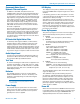
UCR401 Front Panel Controls and Functions LCD MENU Button SEL Up Button Power OFF/ON Switch SEL Down Button LCD Screen The LCD Screen is a graphics-type Liquid Crystal Display that is used to monitor system operation and configure the UCR401. MENU Button The MENU button steps through the four primary windows and setup screens. SELECT Up/Down Buttons The SELECT Up/Down buttons are used to select various options within each display selection and for setting the operating frequency of the receiver.
UHF Digital Hybrid Wireless® Receiver Main Window (LCD) Audio Levels - reference levels for audio signal modulation from transmitter SEL Up Button - control up one step MENU Button - changes windows SEL Down Button control down one step Power ON/OFF switch RF levels - reference for RF level screen icon The Main Window displays information concerning the condition of the Pilot Tone, antenna phase, RF and audio signal levels and battery conditions for both the receiver and the associated transmitter.
UCR401 Menu Selections from Main Window Main Window U ss M s ss M EN U Press MENU Press MENU Press UP Press & Hold MENU SELECT Lock/Unlock EN U U EN Pre M P ress Pres M Level Frequency Scan Mode Pre Setup Window Press UP Press All Buttons Hold MENU & press UP EN Pilot Off/On Frequency Window (Press UP / DOWN to adjust) Press MENU Audio Test Tone Audio Test Tone Press MENU Press UP Press UP (Press UP / DOWN to adjust) Tx Battery Type Press MENU Press UP Press MENU Battery
UHF Digital Hybrid Wireless® Receiver Setup Window In the Setup window, the SEL Up and Down buttons scroll through a list of eight possible setup screens: EXIT, LEVEL, TONE, TXBAT, PHASE, SmtNR (in 400 Series mode only), TUNING and COMPAT. Each of these destinations allows a variety of settings to customize the receiver operating parameters. Pressing the MENU button accesses whatever setup screen is identified in the Setup window.
UCR401 TUNING The Tuning setup screen allows selection of one of four factory set frequency groups (Groups A through D), two user programmable frequency groups (Groups U and V) or the choice to not use groups at all. In the four factory set frequency groups, eight frequencies per group are preselected. These frequencies are chosen to be free of intermodulation products. (See Frequency Coordination.) In the two user programmable frequency groups, up to 16 frequencies can be programmed per group.
UHF Digital Hybrid Wireless® Receiver Frequency Scan Mode Scan & View Window Elements Cursor - shows relative position of the scanner within the 25 MHz band of the receiver. Scan level indications - showing relative level of RF activity across the 25 MHz bandwidth of the receiver. Switch Settings - shows the transmitter switch settings - will change rapidly while the unit is scanning. Remaining unscanned part of band.
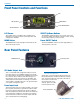
UCR401 Antenna Orientation Two antennas are used in a polarity switching, combining technique called Smart DiversityTM to provide an immunity to dropouts caused by RF multipath reflections. Signals from the transmitter arrive in a direct path from the transmitter and from reflections from other directions. To make full use of diversity reception, the antenna whips need to be spaced apart. Good Bad The whips are made of woven stainless steel and can be bent and shaped without damaging them.
UHF Digital Hybrid Wireless® Receiver Setup and Operating Instructions Installing/Replacing Batteries 1. As per the instructions engraved on the Battery Door, use your thumb to lift and open door. Then rotate it until it is perpendicular with the case. 2. Replace the old batteries, ensuring that you observe the polarity of the batteries when installnig the new ones. Adjusting Audio Output 1. Install fresh batteries or connect an external power source to the UCR401. 2.
UCR401 Warning: A common mistake is to use the transmitter audio gain control to set the overall audio level of the recorder or sound system. The transmitter gain control is only used to set the proper modulation of the transmitter to match the microphone placement and talker’s voice level. Once set it should remain untouched until the microphone, placement or talker changes. 6. Adjust the Audio Output on the receiver for an optimal level for your recorder or sound system.
UHF Digital Hybrid Wireless® Receiver Press all three buttons at the same time to move to Frequency Select Screen To UNLOCK the UCR401 Press and hold the MENU button until a bar tracks horizontally across the screen and the word “UNLOCKED” is displayed on the LCD screen. When the unit is UNLOCKED, all settings can be altered. The UCR401 can only be LOCKED or UNLOCKED from any of the main windows. (There are four of them.
UCR401 Pre-coordinated Frequencies Groupings of compatible frequencies have been created to minimize intermodulation problems in multiple channel wireless systems. The frequencies can be used with Digital Hybrid and analog Lectrosonics wireless equipment. Compatibility with other brands is likely, but not guaranteed by Lectrosonics. FREQ SW SET The uppermost eight frequencies comprise Grp a, the eight just below them comprise Grp b, and so on.
UHF Digital Hybrid Wireless® Receiver Frequency Coordination IM (intermodulation) is a process of two or more RF signals mixing in any stage in the transmitter or receiver that generates another RF signal. If this new signal happens to land on a carrier, IF or oscillator frequency you may have interference problems that affect range or audio quality. The possible combinations also include odd and even order harmonics of the carriers.
UCR401 Pilot Tone Bypass Some wireless equipment uses a supersonic “pilot tone” to control the squelch (audio mute) of a receiver module to keep it silent until a valid signal is received. When a signal with the correct pilot tone is received, the squelch opens and audio is delivered to the output. Pilot tone squelch control also eliminates transients (clicks and pops) when transmitters are turned on and off. Pilot tone is supported in the Digital Hybrid compatibility modes for those systems that use it.
UHF Digital Hybrid Wireless® Receiver Replacement Parts and Accessories CCMINI CCMINI Zippered, padded vinyl system pouch DCR12/A4U Power Supply; 90-240 VAC, 50/60 Hz input; 12 VDC (regulated), 400 mA max. output. VSR1 Thin velcro loop for power cable strain relief. PS70 A/C power supply with 3-pin NEMA socket on housing, 100-240 VAC input; 13.8 VDC, 2.8 A (max.) output. 21425 6 ft. long power cord; coaxial to stripped & tinned leads. Coaxial plug: ID-.080”; OD-.218”; Depth- .5”.
UCR401 Troubleshooting Symptom Possible Cause INITIAL POWER ON LCD display not active or lit External power supply disconnected or inadequate. Wrong polarity power source. The external power input jack requires POSITIVE (+) to be on the center pin. Battery gets warm and doesn’t work. Battery may be low. Try fresh batteries. Version message shows DSP or COM This indicates an internal error. Please contact the factory for assistance.
UHF Digital Hybrid Wireless® Receiver Symptom Possible Cause ANTENNAS AND RF SIGNAL STRENGTH RF Level is weak No RF Signal AUDIO SIGNAL QUALITY Poor signal to noise ratio Receiver may need to be moved or reoriented. Antenna on transmitter or receiver may be defective or poorly connected - double check antennas. Improper length of antenna, or wrong antenna on transmitter or receiver. UHF whip antennas are generally about 3 to 5 inches long.
UCR401 Specifications and Features Operating Frequencies (MHz): Block 470: Block 19: Block 20: Block 21: Block 22: Block 23: Block 24: Block 25: Block 26: Block 27: Block 28: Block 29: Block 944: Frequency Adjustment Range: Channel Seperation: Receiver Type: Frequency Stability: Front end bandwidth: Sensitivity 20 dB Sinad: 60 dB Quieting: Squelch quieting: AM rejection: Modulation acceptance: Image and spurious rejection: Third order intercept: Divers
UHF Digital Hybrid Wireless® Receiver Service and Repair If your system malfunctions, you should attempt to correct or isolate the trouble before concluding that the equipment needs repair. Make sure you have followed the setup procedure and operating instructions. Check the interconnecting cables and then go through the Troubleshooting section in this manual.
LIMITED ONE YEAR WARRANTY The equipment is warranted for one year from date of purchase against defects in materials or workmanship provided it was purchased from an authorized dealer. This warranty does not cover equipment which has been abused or damaged by careless handling or shipping. This warranty does not apply to used or demonstrator equipment. Should any defect develop, Lectrosonics, Inc. will, at our option, repair or replace any defective parts without charge for either parts or labor.