UCR2 11 UCR21 DIVERSITY UHF RECEIVER OPERATING INSTRUCTIONS LECTROSONICS, INC. Rio Rancho, NM www.lectrosonics.
UCR211 2 LECTROSONICS, INC
UHF Compact Receiver TABLE OF CONTENTS GENERAL TECHNICAL DESCRIPTION ............................................................. 4 DIVERSITY RECEPTION ................................................................................ 4 RF FREQUENCY TRACKING FRONT-END AND MIXER ............................... 4 MICROCONTROLLER, PLL AND VCO CIRCUITS ........................................................................................................ 4 IF AMPLIFIERS AND SAW FILTERS ........................
UCR211 GENERAL TECHNICAL DESCRIPTION The UCR211 is a portable, high performance, tripleconversion, frequency synthesized, UHF receiver fully compatible with all Lectrosonics 200 series transmitters. The RF performance is extremely stable over a very wide temperature range, making the UCR211 perfectly suited to the rough environmental conditions found in the field. The proprietary audio processing includes a dualband compandor for very low distortion and a superior signal to noise ratio.
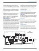
UHF Compact Receiver identify the desired signal and mute all others. (If the transmitter frequency differs from the receiver by as much as one “notch” or 100kHz, the pilot tone indicator on the receiver will drop out and the receiver audio will mute.) adjusting squelching behavior dynamically for the most serviceable result under variable conditions. Using these and other techniques, the UCR211 can deliver accept able audio quality from otherwise unusable signals.
UCR211 also has protection circuits that prevent damage to the receiver if a positive ground power source is applied. LCD DISPLAY The display has four main windows. Pressing the MENU button rotates through each of these windows. If the battery gets low on either transmitter or receiver, a message will interrupt the display every few seconds and flash a “LOW BATTERY” warning.
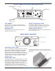
UHF Compact Receiver FRONT PANEL CONTROLS AND INDICATORS SELECT Up Button - control up one step LCD MENU Button 1 2 Pilot 1000 100 10 SEL 1 uV -40 -20 0 dB BAT Div RF Aud LECTRO Rx Tx MENU UCR 211 OFF ON OFF/ON - Power switch SELECT Down Button - control down one step LCD SCREEN SELECT UP/DOWN BUTTONS The LCD Screen is a graphics-type Liquid Crystal Display that is used to monitor system operation and configure the UCR201.
UCR211 MAIN WINDOW (LCD) Audio Levels - reference levels for audio signal modulation from transmitter Msin Window (LCD) 1 Pilot 1000 100 10 SEL 1 uV 2 -40 -20 0 dB BAT Div RF Aud LECTRO Rx Tx MENU UCR 211 OFF ON RF levels reference for RF level screen icon The Main Window displays information concerning the condition of the Pilot Tone, antenna phase, RF and audio signal levels and battery conditions for both the receiver and the associated transmitter.
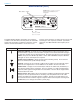
UHF Compact Receiver MENU SELECTIONS FROM MAIN WINDOW Main Window Press All Buttons Frequency Scan Mode Press & Hold MENU SELECT Lock/Unlock Pilot Off/On Hold MENU & press UP U EN M P ress Pres M s M M EN U P r es Press UP Level Pre ss SETUP TONE LEVEL 00 dBu ME NU Press MENU (Press UP / DOWN to adjust) s M EN U Audio Test Tone TONE? 00 dBu Audio Test Tone Press UP LVL 1K 00 dBu Press MENU TX RX ENU ENU TV40 AE 631.
UCR211 FREQUENCY SCAN MODE Scan Freq Window u en ss ny M A Pre USE OLD USE NEW Pre Fine View To Exit Scan Mode, Press All 3 Buttons From Any Window. B8 Press All 3 Buttons ss Bu B8 tton View B8 Press Menu SCAN AND VIEW WINDOW ELEMENTS Cursor - shows relative position of the scanner within the 25Mhz band of the receiver Scan level indications showing relative level of RF activity across the 25MHz bandwidth of the receiver.
UHF Compact Receiver ANTENNA USE AND PLACEMENT The receiver is supplied with two straight BNC antennas. In some circumstances remote antennas such as the SNA600 or ALP700 may be useful for improving recep tion. Position remote antennas at least three or four feet apart and so that they are also not within 3 or 4 feet of large metal surfaces. If this is not possible, try to posi tion the antennas so that they are as far away from the metal surface as is practical.
UCR211 INSTALLATION AND OPERATING INSTRUCTIONS 1. Install a fresh battery or connect an external power source to the UCR211. 2. Unless frequency settings have been previously assigned, scan for an open frequency and set both the receiver and transmitter to that fre quency. (See Finding Clear Frequencies.) 3. Connect the audio cable to the Receiver Audio Out XLR jack. 4. Note The test tone output is especially useful for an exact level match.
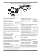
UHF Compact Receiver Vertical marker moves left to right Scan Press the SEL Up arrow button to select USE OLD and return to the frequency that was set before scanning. B8 1000 100 10 1 uV 1 2 Pilot 1000 100 10 SEL 1 uV RF activity Strength of RF activity is indicated in microvolts with markings on the front panel 5. Scan No RF activity (clear channel) 6. If necessary, press the MENU button to zoom in for greater detail for fine adjustment. B8 Fine adjustment can be made when zoomed closer 8.
UCR211 REPLACING THE BATTERY Lift and open the bottom battery door cover with your thumb, rotate the door clockwise until it is perpendicular with the case and allow the battery to fall out of the compartment into your hand. Retaining pins will prevent you from opening too far. It is difficult to install the battery backwards. Observe the large and small holes in the battery contact pad before inserting a new battery.
UHF Compact Receiver UCR211 REPLACEMENT PARTS and ACCESSORIES Part No. 32251 Description . Velcro mounting strips 35753 Zippered, padded vinyl system pouch CH12 AC power supply VSR1 Thin velcro loop for power cable strain relief. A8U UHF marine phosphor bronze antenna - straight connector, specify block.
UCR211 TROUBLESHOOTING POWER SUPPLY AND FUSE LCD display not active PILOT TONE SQUELCH PILOT indicator is solid “P”, but no sound PILOT “P” keeps flashing when transmitter audio switch is turned on Noise on audio and Pilot indicator is “b” • External power supply disconnected or inadequate. • Main power supply fuse tripped. Turn the receiver off, remove the cause of the overload and turn the receiver back on. • Wrong polarity power source. The external DC in requires POSITIVE to be on the center pin.
UHF Compact Receiver SPECIFICATIONS AND FEATURES Operating Frequencies (MHz): Block 21: Block 22: Block 23: and Block 24: Block 25: Block 26: Block 27: Block 28: Block 29: 537.600 - 563.100 563.200 - 588.700 588.800 - 607.900 614.100 - 614.300 614.400 - 639.900 640.000 - 665.500 665.600 - 691.100 691.200 - 716.700 716.800 - 742.300 742.400 - 767.900 Frequency Adjustment Range: 25.5 MHz in 100 kHz steps Receiver Type: Triple conversion, superheterodyne, 244 MHz , 10.
UCR211 SERVICE AND REPAIR If your system malfunctions, you should attempt to correct or isolate the trouble before concluding that the equipment needs repair. Make sure you have followed the setup procedure and operating instructions. Check out the intercon necting cords and then go through the TROUBLESHOOTING section in the manual We strongly recommend that you do not try to repair the equipment yourself and do not have the local repair shop attempt anything other than the simplest repair.
UHF Compact Receiver Rio Rancho, NM – USA 19
LIMITEDONE ONE YEAR LIMITED YEARWARRANTY WARRANTY The equipment is warranted for one year from date of purchase against defects in materials or workmanship provided it was purchased from an authorized dealer. This warranty does not cover equipment which has been abused or damaged by careless handling or shipping. This warranty does not apply to used or demonstrator equipment. Should any defect develop, Lectrosonics, Inc.