UCR210 D DIVERSITY UHF RECEIVER OPERATING INSTRUCTIONS and trouble-shooting guide LECTROSONICS, INC. WWW.LECTROSONICS.
TABLE OF CONTENTS GENERAL TECHNICAL DESCRIPTION .............................................................. 3 FRONT PANEL CONTROLS AND FUNCTIONS .................................................. 6 REAR PANEL CONTROLS AND FUNCTIONS .................................................... 7 ANTENNA USE AND PLACEMENT ..................................................................... 8 INSTALLATION AND OPERATING INSTRUCTIONS ..........................................
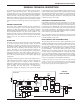
UHF Wireless Diversity Receiver GENERAL TECHNICAL DESCRIPTION The UCR210D is a portable, high performance, triple-conversion, frequency synthesized, UHF receiver. The RF performance is extremely stable over a very wide temperature range, making the UCR210D perfectly suited to the rough environmental conditions found in the field. The proprietary audio processing includes a dual-band compandor for very low distortion and a superior signal to noise ratio.
DOUBLE BALANCED DIODE MIXERS In all wireless receivers, a mixer is used to convert the carrier frequency to the IF frequency where most of the filtering and gain in the receiver takes place. After doing all the right things in the front end, it would be a shame to waste the performance with a second rate mixer. In other designs that is exactly what happens since mediocre mixers cause more intermodulation problems than mediocre front ends.
UHF Wireless Diversity Receiver spond too rapidly and the audio sounds “choppy”, respond too sluggishly and syllables or entire words are cut off. The UCR210D combines several techniques to achieve an optimal balance, removing distracting noise, without the squelching action itself becoming a distraction. One of these techniques involves waiting for a word or syllable to complete before squelching.
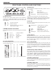
FRONT PANEL CONTROLS AND FUNCTIONS RCVR BAT LED AUX PILOT TONE BYPASS RCVR PT BAT INT EXT PWR PWR OFF RF LEVEL MOD LEVEL AUDIO LEVEL MAIN TX BAT 0° 180° PT LED (Pilot Tone) The audio output muting (squelch) function of the UCR210D is controlled by a 32kHz tone modulation of the RF carrier. The audio output is muted until this tone is present.
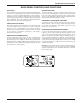
UHF Wireless Diversity Receiver REAR PANEL CONTROLS AND FUNCTIONS DC IN JACK BATTERY RELEASE The UCR210D can be powered from external DC applied directly to this jack (see Specifications and Features section for allowed voltages), or from the supplied CH20 adapter. The UCR210D is protected from reverse polarity conditions which prevents damage if a positive ground power source is applied. The center pin of this jack is POSITIVE.
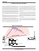
ANTENNA USE AND PLACEMENT The receiver is supplied with two straight BNC antenna. In some circumstances remote anteannas such as the SNA600 or ALP700 may be useful for improving reception. Position remote antennas at least three or four feet apart and so that they are not within 3 or 4 feet of large metal surfaces. If this is not possible, try to position the antennas so that they are as far away from the metal surface as is practical.
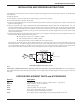
UHF Wireless Diversity Receiver INSTALLATION AND OPERATING INSTRUCTIONS 1. Install batteries or connect the power cord. Batteries should be inserted negative end first into the battery magazine. See the illustration on the magazine. 2. Attach the antennas. 3. Set the frequency switches to match the transmitter frequency switch setting. See page 7. 4. Connect the audio cable to the audio output XLR. 5. Set the front panel Audio Output Level control to minimum and set the Power switch to ON (right position.
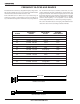
FREQUENCY BLOCKS AND RANGES The table below lists the factory designated frequency ranges avail able for the UCR210D receiver. For convenience, the table includes information about the transmitter antennas as well. Each UCR210D receiver is built to cover a pre-selected range of frequencies (a “block”) as shown below. The receiver will tune to any of 256 different frequencies within this factory assigned block.
UHF Wireless Diversity Receiver TROUBLESHOOTING POWER SUPPLY AND FUSE AUDIO SIGNAL QUALITY LEDs not lit or dimly lit Poor signal to noise ratio • External power supply disconnected or inadequate. • Transmitter gain set too low • Main power supply fuse tripped. Turn the receiver off, remove the cause of the overload and turn the receiver back on. • Noise may not be in wireless system. Mute the audio signal at the transmitter and see if noise remains.
SPECIFICATIONS AND FEATURES Operating Frequencies (MHz): Block 21 537.600 - 563.100 Block 22 563.200 - 588.700 Block 23 588.800 - 614.300 (outside USA) Block 24 614.400 - 639.900 Block 25 640.000 - 665.500 Block 26 665.600 - 691.100 Block 27 691.200 - 716.
UHF Wireless Diversity Receiver SERVICE AND REPAIR If your system malfunctions, you should attempt to correct or isolate the trouble before concluding that the equipment needs repair. Make sure you have followed the setup procedure and operating instructions.
LIMITEDONE ONE YEAR LIMITED YEARWARRANTY WARRANTY The equipment is warranted for one year from date of purchase against defects in materials or workmanship provided it was purchased from an authorized dealer. This warranty does not cover equipment which has been abused or damaged by careless handling or shipping. This warranty does not apply to used or demonstrator equipment. Should any defect develop, Lectrosonics, Inc.