UCR205D DIVERSITY UHF RECEIVER OPERATING INSTRUCTIONS and trouble-shooting guide LECTROSONICS, INC. Rio Rancho, NM www.lectrosonics.
TABLE OF CONTENTS GENERAL TECHNICAL DESCRIPTION ................................................................. 3 FRONT PANEL CONTROLS AND FUNCTIONS ..................................................... 6 REAR PANEL CONTROLS AND FUNCTIONS ....................................................... 7 ANTENNA USE AND PLACEMENT ........................................................................ 8 INSTALLATION AND OPERATING INSTRUCTIONS .............................................
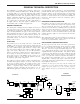
UHF Wireless Diversity Receiver GENERAL TECHNICAL DESCRIPTION The UCR205D is a portable, high performance, dual-conver sion, frequency synthesized, UHF receiver. The RF performance is extremely stable over a very wide temperature range, making the UCR205D perfectly suited to the rough environmental con ditions found in the field. The proprietary audio processing includes a dual-band compandor for very low distortion and a superior signal to noise ratio.
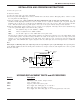
DOUBLE BALANCED DIODE MIXERS In all wireless receivers, a mixer is used to convert the carrier frequency to the IF frequency where most of the filtering and gain in the receiver takes place. After doing all the right things in the front end, it would be a shame to waste the performance with a second rate mixer. In other designs that is exactly what happens since mediocre mixers cause more intermodulation problems than mediocre front ends.
UHF Wireless Diversity Receiver position is useful for locating a clear frequency, since any potential interference may be heard. It may also be used in situations where squelching behavior is undesirable. The “PI LOT OFF” position disables the squelch, as described below. SQUELCH The UCR205D employs a sophisticated squelching system in an attempt to deliver the cleanest possible audio during mar ginal conditions of reception.
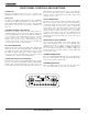
FRONT PANEL CONTROLS AND FUNCTIONS POWER LED When lit, this LED indicates that power is applied to the UCR205D and adequate voltage is present to operate the unit. PILOT LED The audio output muting (squelch) function of the UCR205D is controlled by a 32kHz tone modulation of the RF carrier. The audio output is muted until this tone is present. This green LED will remain on as long as the receiver audio is enabled by the pilot tone.
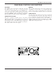
UHF Wireless Diversity Receiver REAR PANEL CONTROLS AND FUNCTIONS DC IN JACK MONITOR The UCR205D can be powered from external 10 to 16.5 Volts DC applied directly to this jack, or conventional 110 VAC sources via the supplied CH20 adapter. The UCR205D is pro tected from reverse polarity conditions which prevents damage if a positive ground power source is applied. The center pin of this jack is POSITIVE. This power connector is threaded to allow the plug to be locked to prevent accidental pull-out.
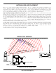
ANTENNA USE AND PLACEMENT “hiss” or a “swishing” sound. Moving the transmitter even a few inches will change the sound of the hum or hiss, or elimi nate it. A drop-out situation may be either better or worse as the crowd fills and/or leaves the room, or when the transmitter or receiver is operated in a different location. There are two remote antenna assemblies included with this receiver.
UHF Wireless Diversity Receiver INSTALLATION AND OPERATING INSTRUCTIONS 1. Connect the power cord. 2. Attach the antennas. 3. Connect the audio cable to the audio output XLR. 4. Set the front panel Audio Output Level control to minimum and set the Power switch to ON (right position.) Check to see that the front panel Power LED lights up. 5. Adjust the transmitter gain. THIS IS PERHAPS THE MOST IMPORTANT STEP IN THE SET UP PROCEDURE.
TROUBLESHOOTING POWER SUPPLY AND FUSE LEDs not lit or dimly lit Poor signal to noise ratio • External power supply disconnected or inadequate. • Transmitter gain set too low • Main power supply fuse tripped. Turn the receiver off, remove the cause of the overload and turn the receiver back on. • Noise may not be in wireless system. Mute the audio signal at the transmitter and see if noise remains. If the noise remains, then turn the power off at the transmitter and see if it remains.
UHF Wireless Diversity Receiver SPECIFICATIONS AND FEATURES 537.600 to 865.000 MHz (537.600 to 767.900 US model) 25.5 MHz max Dual conversion, superheterodyne, 71MHz and 455kHz ±0.
SERVICE AND REPAIR If your system malfunctions, you should attempt to correct or isolate the trouble before concluding that the equipment needs repair. Make sure you have followed the setup procedure and operating instructions. Check out the interconnecting cords and then go through the TROUBLE SHOOTING section in the manual We strongly recommend that you do not try to repair the equipment yourself and do not have the local repair shop attempt anything other than the simplest repair.
This page intentionally blank.
LIMITED ONE ONE YEAR WARRANTY LIMITED YEAR WARRANTY The equipment is warranted for one year from date of purchase against defects in materials or workmanship provided it was purchased from an authorized dealer. This warranty does not cover equipment which has been abused or damaged by careless handling or shipping. This warranty does not apply to used or demonstrator equipment. Should any defect develop, Lectrosonics, Inc.