UCR190 UHF Compact Receiver OPERATING INSTRUCTIONS and trouble-shooting guide LECTROSONICS, INC.
INTRODUCTION Thank you for selecting the Lectrosonics Professional Series wireless microphone system. This system represents well over 10 years of manufacturing experience in wireless microphones, and almost 70 years of design experience. The UCR190 UHF receiver design is the result of surveying the needs of profes sional video producers, ENG cameramen and many others in the broadcast and pro video industry. Hundreds of conversations with dealers and end-users developed the final parameters for the design.
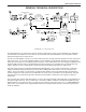
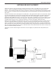
UHF Compact Receiver GENERAL TECHNICAL DESCRIPTION Ant Helical Resonator Double Filter Balanced GAsFET Mixer Preamp 1st IF Amp and Crystal Filters RF LED 2nd Mixer Audio Level Squelch Demodulator Helical Resonator Filter 2nd IF Amp w/LC Filters 1st Local Oscillator AFC 9V Battery Output Amp & Level Control CH12 Jack +9V Reg Polarity Protection 2nd Local Oscillator Off Ext Int Batt Balanced XLR Output 16 kHz Lo-Pass Filter Dual-Band Compandor +9V 0dB LED Power LED Headphone Output Hdph Am
The Dual Band Compandor is driven by a multiple pole active low-pass filter. The filter ensures that supersonic noise will not cause the compandor to increase gain incorrectly. This filter also drives the -20dB and 0dB modulation LEDs. Traditionally, compandors have been a source of distortion in wireless microphone systems. The basic problem with conventional systems is that the attack and decay times are always a compromise.
UHF Compact Receiver EXT/OFF/INT BATT SWITCH Turns the receiver power off and on and selects either internal 9 Volt battery power, or external 12 Volt DC power (of either polarity). POWER LED Glows when the power switch is in the proper position and the battery is good, or when external 12 Volt DC power is properly supplied. If this LED is very dim or does not light up when the switch is turned on, replace the battery or check the connections from the external power source.
RECEIVER REAR PANEL 12 VDC INPUT Connects to the supplied CH-12 AC adapter for powering the receiver from a 110/120V AC source. The receiver may also be powered from external 12 to 18VDC sources using the correct plug (Switchcraft S-760 power plug). A diode bridge is used in the external power input, so that the UCR190 will operate properly from either polarity. AUDIO OUTPUT Supplies a balanced, low impedance output at microphone level. The audio signal is output on pins 2 and 3, while pin 1 is ground.
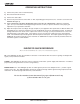
UHF Compact Receiver ANTENNA USE AND PLACEMENT Connect the antenna to the front panel jack. Position the antenna so that it is not within 3 or 4 feet of large metal surfaces. If this is not possible, try to position the antenna so that it is as far away from the metal surface as is practical. It is also good to position the receiver so that there is a direct “line of sight” between the transmitter and the receiver antenna.
OPERATING INSTRUCTIONS 1) Connect the power cord or install the battery. 2) Attach and extend the antenna. 3) Connect the audio cable. 4) Set the front panel switch to either “EXT” or “INT”, depending upon the power source. Check to see that the red POWER LED lights up. 5) THIS IS PERHAPS THE MOST IMPORTANT STEP IN THE SET UP PROCEDURE. Adjust the transmitter “gain”.
UHF Compact Receiver TROUBLESHOOTING Before going through the following chart, be sure that you have a good battery in the receiver (or a properly con nected AC adapter). The POWER LED should glow brightly.
SERVICE AND REPAIR If your system malfunctions, you should attempt to correct or isolate the trouble before concluding that the equipment needs repair. Make sure you have followed the setup procedure and operating instructions. Check out the intercon necting cords and then go through the TROUBLE SHOOTING section in the manual We strongly recommend that you do not try to repair the equipment yourself and do not have the local repair shop attempt anything other than the simplest repair.
UHF Compact Receiver SPECIFICATIONS AND FEATURES Operating Frequencies: 470MHz to 608MHz, crystal controlled Sensitivity: Better than 0.35 uV for 20dB SINAD; 1.5 uV for 50dB S/N ratio Signal/Noise Ratio: 106dB A-weighted Squelch Quieting: greater than 106dB AM Rejection: -60dB (10uV to 0.1 Volts) Modulation Acceptance: ±15kHz Image and Spurious Rejection: greater than 100dB Third Order Intercept: -5 dBm Audio Outputs: XLR: Headphone: 200 Ohms balanced; 100mV max. 0.
LIMITEDONE ONE YEAR LIMITED YEARWARRANTY WARRANTY The equipment is warranted for one year from date of purchase against defects in materials or workmanship provided it was purchased from an authorized dealer. This warranty does not cover equipment which has been abused or damaged by careless handling or shipping. This warranty does not apply to used or demonstrator equipment. Should any defect develop, Lectrosonics, Inc.