UCR110 UHF MULTI-FREQUENCY COMPACT RECEIVER - EURO MODEL OPERATING INSTRUCTIONS and trouble-shooting guide LECTROSONICS, INC.
INTRODUCTION Thank you for selecting the Lectrosonics multi-frequency, UCR110 Receiver. The UCR110 is the result of extensive engineering experience with the very latest micro processor advancements and technology. The Lectrosonics 110 System Receiver and companion transmitter are designed expressly for the most discriminating videographer and for other wireless applications needing superior audio quality, flexible operation, and outstanding durability.
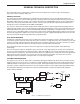
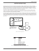
Compact Receiver GENERAL TECHNICAL DESCRIPTION The UCR110 Receiver is comprised of a number of functional subsystems as shown in Fig 1, Block Diagram, Fig 2, Control Panel and Fig 3, Side Panel GENERAL FEATURES The multi-frequency UCR110 FM Receiver is designed to operate with the Lectrosonics UM110 Transmitter and features microprocessor control of 256 frequencies of operation within each frequency block. Each block covers 25.5 MHz with 0.1 MHz frequency spacing. Up to 256 special frequencies and 0.
SAFETY NOTES Excessive sound levels can cause permanent hearing damage. 1. Always adjust the volume to the lowest level before listening to unknown transmissions. 2. Use the lowest reasonable level consistent with hearing safety. 3. Don’t use high sound levels in the earphone to overcome high ambient sound levels. That is abso lutely foolish! Demand and use high isolation earphones. 4. Don’t expose your ears to sound levels that cause them to ring.
Compact Receiver The battery level is precision monitored by the internal microprocessor which also drives the POWER LED for accurate battery condition. IMPORTANT! When the battery voltage drops below 6 Volts, the power LED will remain off, but the other 3 LEDs will light up and a rush of audio noise and distortion will be heard as the squelch opens. This condition is normal, and is easily remedied by replacing the battery.
OPERATING INSTRUCTIONS 1. Install the battery. 2. Set the “FREQUENCY” switches on the side panel to match the switches on the Transmitter. 3. Connect the audio cable. 4. Set the front panel switch to ON. Check to see that the red POWER LED lights up. 5. THIS IS PERHAPS THE MOST IMPORTANT STEP IN THE SET UP PROCEDURE. Adjust the transmitter “gain”. See your transmitter manual (Operating Instructions section) for specific directions on the proper gain adjustment of your particular transmitter. 6.
Compact Receiver BATTERY INSTRUCTIONS The battery you use in the receiver should be a 9 Volt alkaline or lithium, available almost everywhere. An alkaline battery will provide up to 8 hours of operation and a lithium battery will provide up to 20 hours of operation. Carbon zinc batteries, even if marked “heavy duty” will only provide about 2 hours of operation. Rechargeable batteries will only operate the receiver for an hour or less. Make sure your batteries are marked “alkaline” or “lithium.
TROUBLESHOOTING Before going through the following chart, be sure that you have a good battery in the receiver. The POWER LED should glow brightly.
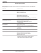
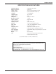
Compact Receiver SPECIFICATIONS AND FEATURES Operating frequencies: Number of frequencies: Channel spacing: Frequency control: Sensitivity: Signal/Noise ratio: 537.600 MHz to 865.
LIMITED YEARWARRANTY WARRANTY LIMITEDONE ONE YEAR The equipment is warranted for one year from date of purchase against defects in materials or workmanship provided it was purchased from an authorized dealer. This warranty does not cover equipment which has been abused or damaged by careless handling or shipping. This warranty does not apply to used or demonstrator equipment. Should any defect develop, Lectrosonics, Inc.