
User Manual


Compact Receiver
Rio Rancho, NM
7
1. Install the battery.
2. Set the “FREQUENCY” switches on the side panel
to match the switches on the Transmitter.
3. Connect the audio cable.
4. Set the front panel switch to ON. Check to see that
the red POWER LED lights up.
5. THIS IS PERHAPS THE MOST IMPORTANT STEP
IN THE SET UP PROCEDURE. Adjust the
transmitter “gain”. See your transmitter manual
(Operating Instructions section) for specific direc-
tions on the proper gain adjustment of your particu-
lar transmitter.
6. Adjust the output control according to the type of in-
put on your equipment. The input levels on different
VCR’s and PA equipment vary, which may require
that you set the output LEVEL control in an interme-
diate position. Try different settings and listen to the
results. If the output of the receiver is too high, you
may hear distortion or a loss of the natural dynam-
ics of the audio signal. If the output is too low, you
may hear steady noise (hiss) along with the audio.
The UCR100 output was designed to drive camera
line level inputs but can operate into camera MIC
inputs if the receiver output is reduced to prevent
Automatic Limiting Control “pumping” in the cam-
era. The output signal level ranges from -50 dBV
with the output control fully counter clockwise to 0
dBV with the output control fully clockwise when the
transmitter signal is at full modulation.
Indicator Quick Reference
RF - This LED lights up when the transmitter is turned
on. This indicates that the receiver is getting an ad-
equate RF signal (carrier) from the transmitter.
POWER - This LED lights up when the receiver is
switched on. It indicates proper battery voltage when
the receiver is using a battery. See chart in Battery
Instructions.
MODULATION - The “-20” LED lights up when an
audio signal is present at an adequate level to produce
a good signal to noise ratio. The “0dB” LED lights up
when the audio level is high and the signal is being
compressed in the transmitter. An extremely high audio
level may cause distortion.
Operating Instructions
Battery Instructions
The battery should be a 9 Volt alkaline or lithium, avail-
able almost everywhere. An alkaline battery will provide
up to 8 hours of operation and a lithium battery will
provide up to 20 hours of operation. Carbon zinc batter-
ies, even if marked “heavy duty” will only provide about
2 hours of operation. Rechargeable batteries will only
operate the receiver for an hour or less. Make sure your
batteries are marked “alkaline” or “lithium.” Short
battery life is almost always caused by weak batteries
or batteries of the wrong type.
A steady “ON” LED corresponds to a fresh battery. The
LED will blink to indicate a low battery condition and
the need for a fresh battery. Continued use will fur-
ther deplete the battery eventually causing the LED to
automatically turn itself off and remain off until a fresh
battery is installed.
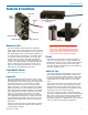
To replace the battery, open the bottom battery door
cover with your thumb, rotate the door until it is perpen-
dicular with the case and allow the battery to fall out of
the compartment into your hand. Observe the large and
small holes in the battery contact pad before inserting
a new battery. Insert the contact end of the battery first,
making sure the contacts are aligned with the holes in
the contact pad, and then swing the door closed. You
will feel it snap into place when it is fully closed.
Hours Power LED
1 Solid On
2 Solid On
3 Solid On
4 Solid On
5 Solid On
6 Blinks 90% on, 10% off
7 Blinks 50% on, 50% off
8 Blinks 10% on, 90% off
9 Off (Replace battery)
1
2