
User Manual


UCR100
LECTROSONICS, INC.
6
1.6M 100K
Audio Level Control
Attenuates the audio output level of the receiver to
match the input requirements of the equipment with
which it is used. The 3.5mm Mini output jack on the
front panel provides an audio output at adjustable levels
for low or high impedance, unbalanced inputs. At the
extreme counter-clockwise position of the control knob,
the output level of the Mini jack will be -50dBV at full
modulation. In the fully clockwise position, the output
level will be 0dBV (1 Vrms) at full modulation. intermedi-
ate settings are sometimes necessary due to the varia-
tions in different input compressors and ALC (automatic
level control) circuits on various VCR’s and audio inputs.
The markings around the control knob are provided
simply as “memory markers;” they are not calibrated
with reference to a specific output level.
Antenna
The antenna is a 1/4 wavelength 50 ohm flexible non-
removable antenna made of durable sheathed bronze
wire.
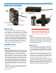
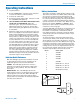
Frequency Select Switches
These two rotary switches adjust the center frequency
of the carrier. The 1.6M is a coarse adjustment and the
100K is the fine adjustment. Each transmitter is factory
aligned at the center of its operating range. The default
position of the frequency select switches is in the center
of the transmitter’s range. The receiver and transmitter
switches must be set to the same number/letter combi-
nation for proper operation.
To gain access to these switches, slide the access door
sideways with a fingernail.
Frequency Select Switches
0
1
2
3
4
5
6
7
8
9
A
B
C
D
E
F
0
1
2
3
4
5
6
7
8
9
A
B
C
D
E
F