
User Manual


Compact Receiver
Rio Rancho, NM
5
Modulation LEDs
The two modulation LED’s indicate the modulation
(audio level) of the incoming signal and can be used for
proper adjustment of the transmitter’s mic or audio level.
The -20 LED glows when the transmitter modulation is
at a high enough level to produce a good audio signal-
to-noise ratio. It will normally flicker, or stay lit as you
speak into the microphone. The 0 dB lamp indicates
a “peak,” showing that the transmitter modulation is at
maximum. Constant lighting of the 0 dB LED indicates
that the audio gain in the transmitter may be set too
high. It is normal and desirable that you see an occa-
sional flicker of the 0 dB lamp in typical use.
Power ON/OFF Switch
Turns the receiver on or off.
Power LED
The Power LED glows when the power switch is in the
ON position and the battery is good. The power LED
starts blinking when the battery is becoming exhausted
and needs replacement. If the LED does not light
up when the switch is turned on or during operation,
replace the battery. In normal operation a new alkaline
battery will operate the receiver approximately 5 hours
before the LED starts blinking and will continue operat-
ing for approximately another 3 hours before the LED
goes off. At that point the unit and the other LED’s
will continue operating for another hour or so but with
some degradation in performance. During the low bat-
tery blinking period the LED on time decreases as the
battery becomes depleated. See the chart in Battery
Instructions.
The battery level is precision monitored by the internal
microprocessor which also drives the Power LED for
accurate battery condition.
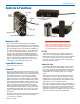
Controls & Functions
IMPORTANT! When the battery voltage drops
below 6 Volts, the power LED will remain off,
but the other 3 LEDs will light up and a rush of
audio noise and distortion will be heard as the
squelch opens. This condition is normal, and
is easily remedied by replacing the battery.
RF LED
Lights when the transmitter is turned on and the re-
ceiver has a strong RF signal. The RF LED will start
blinking when the RF carrier signal from the transmitter
becomes too weak to produce a clean audio signal.
The lamp will go out completely when the RF signal is
absent or extremely weak.
Audio Out Jack
The 3.5mm mini phone jack provides an audio output
that is controlled by the Audio LEVEL control on the
front panel. Generally, the Audio LEVEL control would
be set to provide the proper output level to match the
required level for your video camera or other equip-
ment.
The 3.5mm mini jack will accommodate a mono plug
(tip & sleeve) or a stereo type jack (tip/ring & sleeve)
without harm to the unit. When using a pair of stereo
headphones the audio will be mono but will drive both
earphones in the correct (binaural) phase.
The output at this mini connector jack is designed to
also drive a standard impedance earphone, typically 30
Ohms (most common) and usually provides adequate
volume for setup and testing. The sound from a low
impedance ear phone (ie. 8 Ohms) will not be very loud
and may be distorted at higher listening levels.
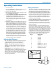
Battery Compartment
Power
ON/OFF
Switch
Modulation LEDs
Audio LEVEL Control
Audio OUT Jack
RF LED
Antenna
Power LED
Frequency Select Switches
(Under Door)