
User Manual


Multi-Frequency IFB Transmitter
Rio Rancho, NM
9
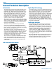
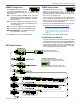
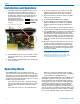
IFBT4 Rear Panel
XLR Jack
A standard XLR female jack accepts a variety of input
sources depending on the setting of the rear panel MODE
switches. XLR pin functions can be changed to suit
the source depending on the positions of the individual
switches. For detailed information on the setting of these
switches see the Installation and Operation section.
MODE Switches
The MODE switches allow the IFBT4 to accommodate
a variety of input source levels by changing the input
sensitivity and the pin functions of the input XLR jack.
Marked on the rear panel are the most common set-
tings. Each setting is detailed below. Switches 1 and
2 adjust the XLR pin functions while switches 3 and 4
adjust the input sensitivity.
Switch
Positions Input
Name 1 2 3 4 XLR Pins Balanced Sensitivity
CC
qqqp 3 = Audio No -10 dBu
1 = Common
MIC pppq 2 = Hi Yes -42 dBu
3 = Lo
1 = Common
LINE
ppqq 2 = Hi Yes 0 dBu
3 = Lo
1 = Common
RTS1 pqqq 2 = Hi No 0 dBu
1 = Common
RTS2 qqqq 3 = Hi No 0 dBu
1 = Common
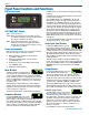
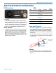
Rear Panel Controls and Functions
Power Input Connector
The IFBT4 is designed to be used with the CH20 exter-
nal (or equivalent) power source. The nominal voltage
to operate the unit is 12 VDC, although it will operate
at voltages as low as 6 VDC and as high as 18 VDC.
External power sources must be able to supply 200 mA
continuously.
The connector dimensions are shown below. Lectroson-
ics P/N 21425 has a straight back shell. P/N 21586 has
a locking collar.
.375” to
.475” typ.
Straight or with
locking collar
Antenna
The ANTENNA connector is a standard 50 ohm BNC
type for use with standard coaxial cabling and remote
antennas.