
User Manual

Multi-Frequency IFB Transmitter
Rio Rancho, NM
13
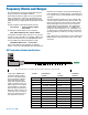
Frequency Blocks and Ranges
The table below lists the factory designated frequency
ranges available for the IFBT4 Transmitter.
Each IFBT4 transmitter is built to cover a pre-selected
range of frequencies (a “block”) as shown below. The
transmitter will tune to any of 256 different frequencies
within this factory assigned block (except blocks 23 and
944).
The block number is determined by this formula:
25.6 × Block =
Lowest frequency (MHz)
in the block
To determine a block number from a frequency:
Freq. (MHz) divided by 25.6 = Block number
It is handy to remember these formulas, in case you do
not have a copy of the table. For example, suppose you
need to know which block covers 685.500 MHz, which
is in the middle of the Block 26 frequency range.
685.500 divided by 25.6 = 26.77734375
The first two digits left of the decimal are the block
number. In this case, 685.500 MHz falls within block 26.
Block 944 is an exception to this block numbering sys-
tem and depicts the actual frequency of the block since
it is a special case in an 8 mHz band with 78 frequency
channels.
The IFB transmitter antennas are color coded to indi-
cate the frequency block that they operate within. The
length of the antenna varies with the frequency block.
The actual length of the antenna is not as critical as
it might appear in the table below. The usable band-
width of the detachable antenna is +/- 50 MHz from
the block’s center frequency, so it is acceptable to use
an antenna from an adjacent block above or below the
operating frequency if some loss in range can be toler-
ated.
Part of block 23 is not used since it covers a 608 to 614
MHz band that is allocated exclusively for use in radio
astronomy.
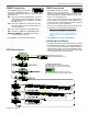
UHF Transmitter Antenna Specifications
Lectrosonics A500RA UHF
transmitter antennas follow
the color code specifications
in the chart below to identify
operating frequency block
range. (The frequency block
range is engraved on the out-
side housing for each individ-
ual transmitter.) If a situation
exists whereby the antenna is
defective and the antenna cap
is missing, refer to the follow-
ing chart to determine the cor-
rect replacement antenna.
BLOCK FREQUENCY CAP ANTENNA
RANGE COLOR LENGTH
470 470.100 - 495.600 Black 5.65”
19 486.400 - 511.900 Black 5.41”
20 512.000 - 537.500 Black 5.01”
21 537.600 - 563.100 Brown 4.75”
22 563.200 - 588.700 Red 4.51”
23 588.800 - 614.300 Orange 4.33”
24 614.400 - 639.900 Yellow 4.14”
25 640.000 - 665.500 Green 3.97”
26 665.600 - 691.100 Blue 3.76”
27 691.200 - 716.700 Violet (Pink) 3.57”
28 716.800 - 742.300 Grey 3.44”
29 742.400 - 767.900 White 3.22”
944 944.100 - 951.900 Black-w/Label 2.49”
33
32
31
21
22
23
24
25
26
27
28
29
30
20
19
470
944
Note: Check the scale of your printout. This line should be 6.00 inches long (152.4 mm).
BL31