INSTRUCTION MANUAL IFBT4 Synthesized UHF IFB Transmitter Includes Firmware Ver. 1.4 Featuring Digital Hybrid Wireless™ Technology U.S. Patent 7,225,135 Fill in for your records: Serial Number: Purchase Date: Rio Rancho, NM, USA www.lectrosonics.
IFBT4 2 LECTROSONICS, INC.
Multi-Frequency IFB Transmitter Table of Contents General Technical Description...............................................................................................................................................................4 Introduction............................................................................................................................................................................................4 Digital Hybrid Technology............................................
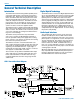
IFBT4 General Technical Description Introduction The IFBT4 IFB transmitter brings DSP capability and a convenient LCD interface to the popular Lectrosonics IFB product line. Replacing the venerable IFBT1 transmitter, the IFBT4 retains the same physical size and is fully interchangeable with its predecessor in terms of audio, RF and power interfaces.
Multi-Frequency IFB Transmitter A user-selectable low frequency roll-off can be set for 35 Hz or 50 Hz. The recommended 50 Hz default setting helps to remove wind and traffic noise, air conditioner rumble, and other sources of undesired low frequency audio. The 35 Hz setting offers a fuller range of sound in the absence of adverse conditions. Input Limiter A DSP-controlled analog audio limiter is employed before the analog-to-digital converter.
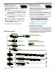
IFBT4 Front Panel Controls and Functions IFBT4 Front Panel In XMIT mode, it is not possible to change the operating frequency. In TUNE mode, the Up and Down buttons may be used to select a new frequency. OFF/TUNE/XMIT Switch OFF Turns the unit off. TUNE Allows all functions of the transmitter to be set up, without transmitting. The operating frequency may only be selected in this mode. XMIT Normal operating position.
Multi-Frequency IFB Transmitter TUNING Setup Screen COMPAT Setup Screen The COMPAT setup screen selects the current compatibility mode, for interoperation with various types of receivers. The available modes are: IFB - Lectrosonics IFB compatibility mode. This is the default setting and is the appropriate setting to use with the Lectrosonics IFBR1A or a compatible IFB receiver. 400 - Lectrosonics 400 Series. This mode offers the best audio quality and is recommended if your receiver supports it.
IFBT4 Frequency Window Behavior, based on TUNING mode selections Adding/Deleting User Programmable Frequency Group Entries If NORMAL tuning mode is selected, the Up and Down buttons select the operating frequency in single channel (100 kHz) increments and the MENU+Up and MENU+Down shortcuts tune in 16 channel (1.6 MHz) increments. Note: Each User Programmable Frequency Group (“u” or “v”) has separate contents.
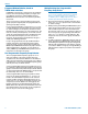
Multi-Frequency IFB Transmitter Rear Panel Controls and Functions IFBT4 Rear Panel XLR Jack A standard XLR female jack accepts a variety of input sources depending on the setting of the rear panel MODE switches. XLR pin functions can be changed to suit the source depending on the positions of the individual switches. For detailed information on the setting of these switches see the Installation and Operation section.
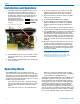
IFBT4 Installation and Operation 1) The IFBT4 transmitter is shipped with pin 1 of the XLR input connector tied directly to ground. If a floating input is desired, a Ground Lift Jumper is provided. This jumper is located inside the unit on the PC board near the rear panel XLR jack. For floating input, open the unit and move the Ground Lift Jumper to the desired location. Location of Ground Lift Jumper: 4) Insert the microphone or other audio source XLR plug into the input jack.
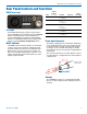
Multi-Frequency IFB Transmitter Accessories CH20 Power supply for IFB base transmitters with locking LZR power jacks; 110 VAC input, 12 VDC regulated output; 400 mA max. CH20 SNA600 SNA600 Collapsible dipole antenna that adjusts over a wide frequency range. Ideal for situations where a full 360 degree receiving pattern is required as opposed to a directional pattern.
IFBT4 Troubleshooting NOTE: Always ensure that the COMPAT (compatibility) setting is the same on both transmitter and receiver. A variety of different symptoms will occur if the settings do not match. With the IFBR1a receiver no sound will be heard unless the transmitter is set to the IFB mode. When used with receivers other than the IFBR1a, a variety of symptoms will occur when the COMPAT settings do not match, ranging from no sound, to level inconsistencies, to distortion of various degrees.
Multi-Frequency IFB Transmitter Frequency Blocks and Ranges Block 944 is an exception to this block numbering system and depicts the actual frequency of the block since it is a special case in an 8 mHz band with 78 frequency channels. The table below lists the factory designated frequency ranges available for the IFBT4 Transmitter. Each IFBT4 transmitter is built to cover a pre-selected range of frequencies (a “block”) as shown below.
IFBT4 Specifications Operating Frequencies (MHz): Block 470 470.100 - 495.600 Block 19 486.400 - 511.900 Block 20 512.000 - 537.500 Block 21 537.600 - 563.100 Block 22 563.200 - 588.700 Block 23 588.800 - 607.900 and 614.100 - 614.300 Block 24 614.400 - 639.900 Block 25 640.000 - 665.500 Block 26 665.600 - 691.100 Block 27 691.200 - 716.700 (export only) Block 28 716.800 - 742.300 (export only) Block 29 742.400 - 767.900 (export only) Block 944 944.100 - 951.
Multi-Frequency IFB Transmitter Service and Repair If your system malfunctions, you should attempt to correct or isolate the trouble before concluding that the equipment needs repair. Make sure you have followed the setup procedure and operating instructions. Check the interconnecting cables and then go through the Troubleshooting section in this manual.
LIMITED ONE YEAR WARRANTY The equipment is warranted for one year from date of purchase against defects in materials or workmanship provided it was purchased from an authorized dealer. This warranty does not cover equipment which has been abused or damaged by careless handling or shipping. This warranty does not apply to used or demonstrator equipment. Should any defect develop, Lectrosonics, Inc. will, at our option, repair or replace any defective parts without charge for either parts or labor.