INSTRUCTION MANUAL T1 Multi-Frequency IFB Transmitter Fill in for your records: Serial Number: Purchase Date: Rio Rancho, NM, USA www.lectrosonics.
T1 2 LECTROSONICS, INC.
Multi-Frequency IFB Transmitter Table of Contents Introduction ............................................................................................................................................................................................ 4 General Technical Description .............................................................................................................................................................. 5 Audio Input Interface ............................................
T1 Introduction Thank you for selecting the Lectrosonics frequency agile, narrowband, T1 IFB (Interruptible Foldback) transmitter. The T1 is the result of over 80 years of engineering experience with the very latest compo nents, in a design that addresses the most demanding professional applications. The Lectrosonics T1 IFB Transmitter along with the companion R1 or R1a IFB Receivers allow on-air talent to monitor program audio and receive cues from directors and other production personnel.
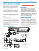
Multi-Frequency IFB Transmitter General Technical Description The T1 IFB Transmitter is comprised of a number of functional subsystems, including Audio Input Interface, Audio Processor, Pilot Tone, Frequency Synthesizer, Microcontroller, Transmitter, Antenna System and Power Supply. (See block diagram.
T1 Pilot Tone The T1/R1A system uses an ultrasonic tone modulation of the carrier to operate the receiver squelch. This “pilot tone” consists of a 29.997 kHz signal which is mixed with the audio signal just after the compandor. The pilot tone controls the audio output muting of the receiver and is filtered out of the audio signal immediately after the detector in the receiver so that it does not influence the compandor or various gain stages.
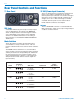
Multi-Frequency IFB Transmitter Front Panel Controls and Functions T1 Front Panel OFF/TUNE/XMIT Switch OFF TUNE XMIT Turns the unit off. Mutes the transmitter section while enabling the up and down frequency buttons for setting the operating frequency of the transmitter. Normal operating position.
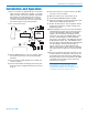
T1 Rear Panel Controls and Functions T1 Rear Panel 12 VDC (Power Input Connector) The T1 is designed to be used with the CH20 external power source, which is plugged into the 12 VDC external power input connector. The nominal voltage to operate the unit is 12 VDC; although it will operate at voltages as low as 11 VDC and as high as 18 VDC. A suitable alternate power source must be able to handle 250 mA continuous consumption.
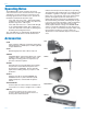
Multi-Frequency IFB Transmitter Installation and Operation 1) The T1 transmitter is shipped with pin 1 of the XLR input connector tied directly to ground. If a floating input is desired, a Ground Lift Jumper is provided. This jumper is located inside the unit on the PC board near the rear panel XLR jack. If a floating connection is desired, open the unit and move the Ground Lift Jumper to the desired location. 5) Attach the antenna (or antenna cable) to the BNC connector on the rear panel.
T1 Operating Notes The AUDIO LEVEL control should not be used to control the volume of the associated receiver. This gain adjustment is used to match the T1 input level to the incoming signal from the sound source to provide full modulation and maximum dynamic range. If the audio level is too high — both LEDs will light frequently or stay lit. This condition may reduce the dynamic range of the audio signal. If the audio level is too low — neither LED will light, or the -20 LED will glow dimly.
Multi-Frequency IFB Transmitter Troubleshooting Symptom: Possible Cause: Display Dead or Blinking On and Off 1) External power supply disconnected or inadequate. 2) The External DC power input is protected by an auto-reset polyfuse. Disconnect power and wait about 10 seconds for the fuse to reset. No Transmitter Modulation LEDs 1) AUDIO LEVEL turned all the way down. 2) Sound source off or malfunctioning. 3) Input cable damaged or mis-wired. No Received Signal 1) Transmitter not turned on.
T1 Frequency Blocks and Ranges The table below lists the factory designated frequency ranges available for the T1 IFB Transmitter. Each T1 transmitter is built to cover a pre-selected range of frequencies (a “block”) as shown below. The transmitter will tune to any of 256 different frequencies within this factory assigned block. The block number is determined by this formula: 25.6 × Freq. (MHz) = Lowest freq. (MHz) in the block To determine a block number from a frequency: Freq. (MHz) divided by 25.
Multi-Frequency IFB Transmitter Specifications Operating Frequencies: Block 21 Block 22 Block 23 Block 24 Frequencies (Channels per block): Channel Spacing: Spurious & Harmonic Suppression: 4 nW at freq.
T1 Service and Repair If your system malfunctions, you should attempt to correct or isolate the trouble before concluding that the equipment needs repair. Make sure you have followed the setup procedure and operating instructions. Check the interconnect ing cables and then go through the TROUBLESHOOTING section in this manual. We strongly recommend that you do not try to repair the equipment yourself and do not have the local repair shop attempt anything other than the simplest repair.
Multi-Frequency IFB Transmitter Rio Rancho, NM 15
LIMITED ONE YEAR WARRANTY The equipment is warranted for one year from date of purchase against defects in materials or workmanship provided it was purchased from an authorized dealer. This warranty does not cover equipment which has been abused or damaged by careless handling or shipping. This warranty does not apply to used or demonstrator equipment. Should any defect develop, Lectrosonics, Inc. will, at our option, repair or replace any defective parts without charge for either parts or labor.