
User's Manual

Micro Body Pack Transmitter
Rio Rancho, NM
11
Microphone Wiring
Looking into the 3 pin Lemo mic connector from the
outside of the transmitter, the pin centered in the two
guide slots is pin 1 (ground). Pin 2 is a 1k resistor to
ground. Pin 3 is the audio/bias connection for two-wire
microphones and line inputs.
Pin 1
Pin 2
Pin 3
Guide slots
Voltages, polarity, impedance and line level for all signal
sources are selected by menus. Menu selections in-
clude presets for popular microphones, and a sub-menu
for manual setup. Refer to the section entitled Setup
Screens on the previous page for details.
Two-wire electret lavaliere:
Pin 1 - Ground (shield)
Pin 3 - Audio and Bias
Sanken COS-11 lavaliere
Recommended Wiring:
Pin 1 - Shield (ground)
Pin 2 - White (audio hot)
Pin 3 - Black (DC power)
NOTE: The COS-11 can also be wired in a two-
wire configuration. Contact Plus24/Sanken for
details.
The Sanken CUB-01 is not supported.
Line Input Wiring and Use
When connecting a line level audio signal to the SSM
input, the line input must be selected on the UP Arrow
menu, and the audio input gain must be set at 44
(maximum) to allow the full range of limiting. Set up this
way the transmitter will cleanly handle input levels up to
0dBV (1 volt).
Line Input:
Pin 1: Shield (ground)
Pin 3: Audio and Bias
Transmitter Settings:
Input Setting
Gain Setting
Note: This gain setting may seem “backwards” or
illogical, however, it is correct due to the unique
nature of the SSM input circuitry.
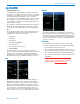
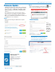
Adjusting the Input Gain
The two bicolor Modulation LEDs on the control panel
provide a visual indication of the audio signal level
entering the transmitter. The LEDs will glow either red
or green to indicate modulation levels as shown in the
following table.
Signal Level -20 LED -10 LED
Less than -20 dB Off Off
-20 dB to -10 dB Green Off
-10 dB to +0 dB
Green Green
+0 dB to +10 dB Red Green
Greater than +10 dB Red Red
NOTE: Full modulation is achieved at 0 dB, when
the “-20” LED first turns red. The limiter can cleanly
handle peaks up to 30 dB above this point.
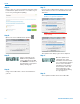
It is best to go through the following procedure with the
transmitter in the standby mode so that no audio will en-
ter the sound system or recorder during adjustment.
1) With a charged battery in the transmitter, power the
unit on in the standby mode (see previous section
Powering On in Standby Mode).
2) Press and hold the AUDIO button with Aud and a
numeral on the display (e.g. Aud 22).
3) Prepare the signal source. Position a microphone the
way it will be used in actual operation and have the
user speak or sing at the loudest level that occur
during use, or set the output level of the instrument
or audio device to the maximum level that will be
used.
4) Use the
and arrow buttons to adjust the gain until
the –10 dB glows green and the –20 dB LED starts
to flicker red during the loudest peaks in the audio.
5) Once the audio gain has been set, the signal can
be sent through the sound system for overall level
adjustments, monitor settings, etc.
6) If the audio output level of the receiver is too high or
low, use only the controls on the receiver to make
adjustments. Unless the microphone or its position
changes, or a different instrument is being used,
leave the transmitter gain adjustment set accord-
ing to these instructions. Use the audio output level
control on the receiver to make adjustments for
the desired level being delivered to the connected
mixer, recorder, etc.