
User's Manual
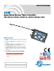

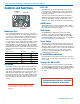

Micro Body Pack Transmitter
Rio Rancho, NM
9
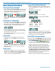
Setup Steps
The setup menus are accessed by holding either the
UP or DOWN arrow while powering the unit on. Refer
to Setup Screens on the next page for details of each
setup parameter.
The following list outlines the steps necessary to set up
the transmitter for normal use.
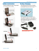
1) Install a charged battery.
2) Set the compatibility mode to match the receiver to
be used.
3) Adjust the step size and frequency to match the
receiver. The frequency is normally determined us-
ing the receiver to identify one within clear operat-
ing spectrum. Refer to the receiver instructions for
details on using features such as scanning.
NOTE: Some Lectrosonics receivers include an
IR (infrared) port to transfer settings from the
receiver to the transmitter. Refer to the section on
IR (infrared) Sync for details.
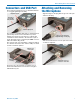
4) Connect the microphone or audio source to be
used. Select the correct input configuration.
5) Adjust the input gain. Refer to Adjusting the Input
Gain for details.
6) Turn on the receiver and verify that solid RF and
audio signals are present (see receiver manual).
Locking the Controls
The firmware version is displayed briefly when powering
up the transmitter.
For firmware versions 1.06 and lower:
Lock the controls by holding the UP and DOWN ar-
rows until a count displayed on the LCD is completed
and Loc appears on the LCD. To unlock the controls,
remove the battery.
For firmware versions 1.07 and higher:
Lock the controls by holding the UP and DOWN arrows
until a count displayed on the LCD is completed and
Loc appears on the LCD. To unlock the controls, hold
the UP and DOWN arrows until a count on the LCD is
completed and unloc appears on the LCD. Removing
the battery does not unlock the controls.
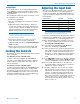
Adjusting the Input Gain
The two bicolor Modulation LEDs on the control panel
provide a visual indication of the audio signal level
entering the transmitter. The LEDs will glow either red
or green to indicate modulation levels as shown in the
following table.
Signal Level -20 LED -10 LED
Less than -20 dB Off Off
-20 dB to -10 dB
Green Off
-10 dB to +0 dB
Green Green
+0 dB to +10 dB Red Green
Greater than +10 dB Red Red
NOTE: Full modulation is achieved at 0 dB, when
the “-20” LED first turns red. The limiter can cleanly
handle peaks up to 30 dB above this point.
It is best to go through the following procedure with the
transmitter in the standby mode so that no audio will en-
ter the sound system or recorder during adjustment.
1) With a charged battery in the transmitter, power the
unit on in the standby mode (see previous section
Powering On in Standby Mode).
2) Press and hold the AUDIO button with Aud and a
numeral on the display (e.g. Aud 22).
3) Prepare the signal source. Position a microphone the
way it will be used in actual operation and have the
user speak or sing at the loudest level that occur
during use, or set the output level of the instrument
or audio device to the maximum level that will be
used.
4) Use the
and arrow buttons to adjust the gain until
the –10 dB glows green and the –20 dB LED starts
to flicker red during the loudest peaks in the audio.
5) Once the audio gain has been set, the signal can
be sent through the sound system for overall level
adjustments, monitor settings, etc.
6) If the audio output level of the receiver is too high or
low, use only the controls on the receiver to make
adjustments. Unless the microphone or its position
changes, or a different instrument is being used,
leave the transmitter gain adjustment set accord-
ing to these instructions. Use the audio output level
control on the receiver to make adjustments for
the desired level being delivered to the connected
mixer, recorder, etc.