
User's Manual
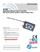


SSM, SSM-941, SSM/E01, SSM/E02, SSM/E06, SSM/X
LECTROSONICS, INC.
8
Operating Instructions
Powering On in Operating Mode
Press and hold the Power Button for several seconds
until a counter on the LCD progresses from 1 through
3, followed by a display of the model, firmware version,
frequency block and compatibility mode.
When you release the button, the unit will be operation-
al with the RF output turned on and the Main Window
displayed.
Powering On in Standby Mode
A brief press of the Power Button , releasing it before
the counter has reached 3, will turn the unit on with the
RF output turned off. The LCD will display a reminder
that the RF output of the transmitter is turned off.
In this Standby Mode the frequency can be browsed
to make adjustments without the risk of interfering with
other wireless systems nearby.
After adjustments are made, press the power button
again to turn the unit off.
Powering Off
Holding the Power Button in and waiting for the
completion of the countdown from 3 to 1 will turn the
power off.
If the power button is released before the countdown is
completed, the unit will remain turned on and the LCD
will return to the same screen or menu that was dis-
played previously.
Setup Screens
Two different setup menus are accessed by holding
either the UP or DOWN arrow button while powering
the unit on. See the following page (Setup Screens) for
a listing of the menu items and descriptions.
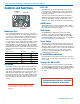
Screens Used in Normal Operation
When the transmitter is turned on with the RF output
on, the LCD will display the frequency, audio gain or LF
roll-off point.
Audio gain is expressed in dB.
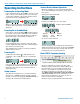
Frequency is displayed in one of two ways:
Frequency expressed in MHz
Standard
frequency
block (22)
Frequency
in hex
code (C8)
Offset in
MHz (.75)
LF roll-off is expressed in Hz.
To make changes to the settings, press either button to
display the desired screen, then use the UP and DOWN
arrows to select the value. The changes take effect im-
mediately when you release the buttons.
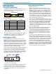
Block 470/19 Frequency Overlap
Frequencies 486.400 - 495.600 Overlap in Blocks 470 and 19
Block 470 and block 19 overlap each other in the
frequency range from 486.400 to 495.600 MHz. Since
block 470 starts at a lower frequency than block 19,
the hex codes (and pilot tones) will not match even
though the frequencies are the same in the overlap
zone. When using a transmitter on the A1 band with
a block 19 receiver, be sure the transmitter is set to
block 19 and check the hex code on the receiver to
make sure it matches the transmitter.
Call the factory if you have questions about this issue.