
User's Manual


Micro Body Pack Transmitter
Rio Rancho, NM
11
Microphone Wiring
Looking into the 3 pin Lemo mic connector from the
outside of the transmitter, the pin centered in the two
guide slots is pin 1 (ground). Pin 2 is a 1k resistor to
ground. Pin 3 is the audio/bias connection for two-wire
microphones and line inputs.
Pin 1
Pin 2
Pin 3
Guide slots
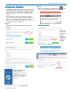
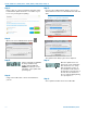
Voltages, polarity, impedance and line level for all signal
sources are selected by menus. Menu selections in-
clude presets for popular microphones, and a sub-menu
for manual setup. Refer to the section entitled Setup
Screens on the previous page for details.
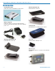
Two-wire electret lavaliere:
Pin 1 - Ground (shield)
Pin 3 - Audio and Bias
Sanken COS-11 lavaliere
Recommended Wiring:
Pin 1 - Shield (ground)
Pin 2 - White (source load)
Pin 3 - Black (bias and audio)
NOTE: The COS-11 can also be wired in a two-
wire configuration. Contact Plus24/Sanken for
details.
The Sanken CUB-01 is not supported.
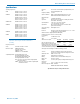
Line Input Wiring and Use
Pin Configuration:
Pin 1: Shield (ground)
Pin 2: Audio
Transmitter Settings:
Input Setting
Unlike the old configuration,
the new line input configura-
tion requires no fixed gain
setting. The gain setting can
be adjusted as needed for
the specific input level used.
Old Configuration:
Pin 1: Shield (ground)
Pin 3: Audio and bias
NOTE: This line input configuration is found on the
following serial numbers and lower:
- Band A1 S/N 2884 and lower
- Band B1 S/N 2919 and lower
- Band C1 all S/Ns
Transmitter Settings:
Input Setting
Gain Setting
Note: This gain setting may seem “backwards” or
illogical, however, it is correct due to the unique
nature of the SSM input circuitry.Input Jack
Configuration
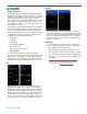
Input Jack Configuration
Looking into the 3 pin Lemo mic connector from the
outside of the transmitter, the pin centered in the two
guide slots is pin 1 and is ground. At 7 o’clock is pin 2
with a 2k resistor to ground. That 2k is a source load
for the Sanken COS-11 to save putting a resistor in the
connector. At 4 o’clock is pin 3, the servo audio input.
Pin 1 - ground
Pin 2 - 2k source load to ground
Pin 3 - servo input
Voltages, phase, impedance, and line level for all mics
signal sources are selected by menus. Pin 3 is the only
connection for all mics except for the aforementioned
Sanken COS-11. Countryman, DPA, Sanken COS-11
and standard two wire mics can be configured in the
menus. The Sanken CUB-01 is not supported.
Locking the Controls
The keypad can be locked to prevent inadvertent
changes to be made to the transmitter. Press and hold
both the UP and DOWN arrow buttons for several
seconds until a countdown is completed on the LCD.
The display will show unloc 3...2...1 and then Loc will
appear. To unlock, remove the batteries.
NOTE: This function is NOT affected, either locked
or unlocked, by turning the power off.