
User's Manual


UHF Digital Hybrid Wireless
®
Rio Rancho, NM
5
General Technical Description
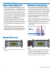
The dual receiver architecture allows two different types
of diversity reception:
SmartDiversity
™
allows each receiver to run indepen-
dently to provide two separate audio channels. The
algorithm analyzes both the incoming RF level and the
rate of change in RF level to determine the optimum
timing for antenna phase switching. The system also
employs “opportunistic switching” to analyze and then
latch the phase in the best position during brief squelch
activity.
Ratio Diversity blends the audio outputs of both receiv-
ers in a seamless manner to produce a single audio
output. A panning circuit blends more signal from the re-
ceiver with the stronger RF signal over a wide RF level
range to anticipate and eliminate dropouts long before
they occur. When a good RF signal is present at both
receivers and the audio is blended equally, the signal-
to-noise ratio is increased by 3 dB.
The design consists of two separate receivers built into
a single, ultra compact housing with interchangeable
adapters for video camera wireless receiver slots and
stand-alone use. Digital Hybrid Wireless
®
technology
provides superb, compandor-free audio quality and
compatibility with other wireless systems. The RF per-
formance is extremely stable over a very wide tempera-
ture range, making the receiver perfectly suited to the
rough environmental conditions in field production.
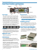
The front panel features a menu-driven LCD interface
and four membrane switches used to view and alter set-
tings. Audio outputs are provided on the rear panel for
camera slots or other audio devices, on the SRC model,
and the SRc5P, model provides a second audio output
on the front panel through a 5-pin TA Series connector.
A built-in spectrum analyzer scans across the tuning
range of the receiver to simplify finding clear operating
frequencies.
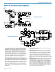
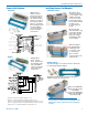
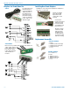
RF PCB Block Diagram
Audio PCB Block Diagram
DSP
Keypad
LCD
display
DAC
Codec
Memory
Ref xtal
Audio 1
Audio 2
(from RF PCB)
To both PLL
To phase switches
Audio amps
Digital pot
Digital pot
µP
digital
atten
CH 1
audio switch
CH 2
audio switch
Fuse
Osc
sync
DC-DC
conv
DC-DC
conv
DC-DC
conv
On/O
–5V
+5V
Osc
sync
+1.6V
+3.3V
V Reg
+3.3V
5k
5k
50
50
+
–
Com
Hi
Lo
+5V
+5V
5k
5k
50
50
+
–
Com
Hi
Lo
+5V
+5V
Diode
protected
outputs
1
2
3
4
5
µP
polarity
µP
Power
DC-DC
conv
+30V
Ref. Osc
Splitter
Phase
combiner
Mixer
IF
amp
SAW
filter
SAW
filter
IF
amp
Rx IC
250 kHz
RSSI
Window
detect
Audio 1
Pulse
detector
1st
VCO
2nd
VCO
PLL
Splitter
Mixer
IF
amp
SAW
filter
SAW
filter
IF
amp
Rx IC
350 kHz
RSSI
Window
detect
Audio 2
Pulse
detector
1st
VCO
2nd
VCO
PLL
Receiver 1
Receiver 2
High side
injection
High side
injection
SRC Dual Receiver RF Board
Phase
combiner
248.450
MHz
243.950
MHz
BPF
LNA
LNA
Tracking
Tracking
µP
µP
BPF
LNA
LNA
Tracking
Tracking