
User's Manual

UHF Digital Hybrid Wireless
®
Rio Rancho, NM
25
26
BD
Block
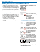
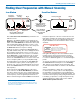
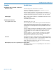
Cursors blink to indicate the
currently selected receiver
RF activity level
Receiver 1,
dashed line
Freq in hex
Receiver 2,
solid line
First, turn off all of the transmitters you intend to use
with the receiver.
Navigate to the SETUP>SCAN screen and press the
MENU/SEL button to start the scanner. The display will
switch to the Scan Window (see illustration above) and
start scanning immediately. Allow the receiver to scan
across the entire tuning range at least once, then press
the MENU/SEL button to stop the scanning.
When the receiver is configured for SWITCHED diver-
sity (dual channel mode), two cursors will appear when
the scanning is stopped. The cursor for receiver 1 is a
dashed line and the cursor for receiver 2 is a solid line.
Press MENU/SEL to toggle between the two receivers
(selected channel will blink). Select the channel and
use the UP and DOWN buttons to move the cursor and
locate a frequency with no (or very weak) RF activity.
Scroll through the screen with the UP and DOWN but-
tons and find a frequency where no RF signals (or in
the worst case, only very weak RF signals) are present.
Press the PWR/BACK button to set the receiver to this
new frequency.
Press both the UP and DOWN buttons at the same
time to switch to the Zoom View Window (see illustra-
tion above). In this view, the cursor remains fixed in the
center of the screen and the background scrolls behind
it. The frequency can be stepped up and down in 100
kHz increments using the UP and DOWN arrow buttons.
NOTE: The appearance of the cursors as described
above started with firmware v1.15. In previous versions
the selected cursor would appear as a dashed line, and
neither cursor would blink.
Keep the frequencies of the two receivers at least 700
kHz apart to minimize de-sensing (short range) issues.
This spacing is a “worst case” approximation assum-
ing the transmitters are about 25 feet from the receiver
antennas.
IMPORTANT:
FREQ.
WARNING
Performance will be degraded if
Receiver 2 is set 4.2 to 4.8 MHz higher
than Receiver 1. The LCD will also flash
this message periodically.
Data gathered during a scan is stored until it is inten-
tionally erased or the power is turned off. Previous
data will remain and subsequent scans can be made
to search for additional signals or to accumulate higher
peaks.
To clear the scan memory and screens, press and hold
the PWR/BACK button briefly. As soon as Powering
off... appears on the display, release the button. The
receiver will remain turned on, and the scan data will be
erased.
Set your transmitter/s to match the corresponding
receiver/s (CH1 or CH2) on the receiver display. Turn
the transmitter on and verify that a strong RF signal is
present. If your transmitter has an IR (infrared) port, you
can transfer the frequency setting using the IR interface.
It is always good practice to verify the frequencies by
going through the procedure in the section entitled
Multi-channel System Checkout.
Scan Window
Zoom View Window
Press both UP and
DOWN arrows on
control panel to switch
to the Zoom View
Press the BACK
button to return
to the Scan View
Window
Cursor (center bar)
Freq in
hex
C7
25
Block
Finding Clear Frequencies with Manual Scanning