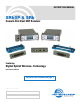
INSTRUCTION MANUAL SRb5P & SRb Camera Slot Dual UHF Receiver Featuring Digital Hybrid Wireless® Technology U.S. Patent 7,225,135 See Quick Start Summary on page 2 Fill in for your records: Serial Number: Purchase Date: Rio Rancho, NM, USA www.lectrosonics.
SRb5P and SRb Dual Receivers Quick Start Summary The following checklist includes the minimum required settings to start using the receiver. • Install either stand-alone or camera slot adapter kit, the antennas and position the receiver as it will be used (see pages 9-12). • Connect power to the receiver (see pages 10,11). • Set the DIVMODE for single or dual channel operation (see page 15,16). • Set the COMPAT (compatibility) mode for the transmitters to be used (see pages 15,16).
UHF Digital Hybrid Wireless® Table of Contents Digital Hybrid Wireless®..................................................................................................... 4 Model Differences.................................................................... 4 SRb........................................................................................ 4 SRb5P.................................................................................... 4 General Technical Description.................................
SRb5P and SRb Dual Receivers Digital Hybrid Wireless® The Lectrosonics Digital Hybrid Wireless® uses innovative technology to combine the advantages of digital audio with the advantages of analog RF transmission. The result delivers the superior sound quality of a digital system and the excellent range of an analog system. A proprietary algorithm encodes the digital audio information into an analog format which can be transmitted in a robust manner over an analog FM wireless link.
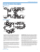
UHF Digital Hybrid Wireless® General Technical Description RF PCB Block Diagram SAW filter Receiver 1 Splitter IF amp Mixer RF amp 248.450 MHz IF amp SAW filter 350 kHz SAW filter µP Phase combiner 1st VCO High side injection Phase combiner SAW filter Audio 1 Window detect 2nd VCO RSSI PLL SR Dual Receiver RF Board Ref. Osc Receiver 2 Pulse detector Rx IC PLL RSSI High side injection 2nd VCO 1st VCO Splitter Window detect µP RF amp IF amp Mixer SAW filter 243.
SRb5P and SRb Dual Receivers RF Front-End and Mixer Each antenna signal is first passed through a high quality SAW filter to reject high power RF signals above and below the operating frequency. A high current amplifier follows the SAW filters and passes the signal to an internal splitter so that both antenna signals are available to both receivers for SmartDiversity™ reception.
UHF Digital Hybrid Wireless® The Smart Noise Reduction algorithm has three modes, selectable from a user setup screen. The optimal setting for each application is subjective and selected while simply listening. • OFF defeats noise reduction and complete transparency is preserved. All signals presented to the transmitter’s analog front end, including any faint microphone hiss, will be faithfully reproduced at the receiver output.
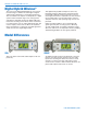
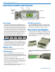
SRb5P and SRb Dual Receivers Front Panel Controls and Functions Receiver 1 Receiver 2 MENU/SELECT Button UP Button Audio Output DOWN Button POWER/BACK Button LCD Main Window with two channels shown Audio Outputs UP/DOWN Arrow Buttons A second set of audio outputs is provided next to the front panel for use with cameras that have only one audio channel enabled in the slot.
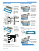
UHF Digital Hybrid Wireless® Camera Slot Adapters Installing Camera Slot Adapters SRUNI SRUNI Adapter Thread two short screws through the recessed tabs on the adapter and slide it onto the receiver housing. Thread two short screws through the tabs on the receiver flange as shown. Adapter kit for Unislot® camera slots such as those provided on Ikegami® and Panasonic® cameras.* Includes bezel, hardware and rear panel DB25 connector wired for power and audio connections.
SRb5P and SRb Dual Receivers Adapters for Stand-Alone Use SREXT For stand-alone use, this kit includes a rear panel with two TA3 male jacks for the balanced outputs and a power jack with a locking connector. Trim the power cable to the desired length. Installing Rear Panel Adapters Installation of the rear panel output/power adapters is the same for all models. Panels are held in place by two phillips head screws on the sides of the housing.
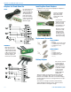
UHF Digital Hybrid Wireless® Audio Output Cables External Power Cables MCSR5PXLR5P 21747 Locking LZR style plug to stripped and tinned; 6 feet long. Right angle TA5F plug to 5-pin XLR; balanced outputs; 25 inches long. For TA5M output jacks. MCSR5PXLR2 Right angle TA5F plug to two 3-pin XLR; balanced outputs; 20 inches long. For TA5M output jacks. RATPAC Adapter Kit Adapter kit to build either a 3-pin or 5-pin TA Series right angle connector.
SRb5P and SRb Dual Receivers Mounting and Orientation Installation into the slot on a video camera places the antennas in an optimal vertical position away from the camera body. When used with non-slot cameras, as depicted in the diagram below, one or two receivers can be positioned in a variety of locations around the camera body using the Velcro and SRSLEEVE mounting options.
UHF Digital Hybrid Wireless® Whip Antennas Lectrosonics AMM Series UHF transmitter antennas follow the labeling specifications in the chart below to identify operating frequency block. If the antenna cap or label is missing, refer to the following chart to determine the frequency of the antenna. The frequency block is engraved on the outside of the receiver housing. 470 740 19 20 21 22 23 24 25 26 27 28 31 30 29 32 33 779 944 Whip Length Note: Check the scale of your printout.
SRb5P and SRb Dual Receivers LCD Main Window Receiver 1 Receiver 2 RF Level Diversity Activity Audio Level Pilot Tone Indicator The Main Window displays information concerning the condition of the Pilot Tone, antenna phase, RF and audio signal levels and battery conditions for both the receiver and the associated transmitter.
UHF Digital Hybrid Wireless® Navigating the LCD Receiver 1 Pilot Tone ON\OFF Hold MENU and press UP momentarily Receiver 2 Pilot Tone ON/OFF Hold MENU and press DOWN momentarily Main Window Hold MENU and hold UP Mute Audio on Receiver 1 Hold MENU and hold DOWN Mute Audio on Receiver 2 NOTE: Press the BACK button from the Main Window to briefly display the external power supply voltage. BACK Setup Screen SETUP (item) MENU BACK MENU Press UP/DOWN to select 2 BACK MENU 1 80 652.
SRb5P and SRb Dual Receivers Main Window Menu Items The appearance of the LCD Main Window will change according to which diversity mode is selected: • SWITCH (2-channel mode) splits the screen to indicate activity and levels on both receivers and transmitters. • RATIO combines the audio outputs of both receivers to deliver a single audio channel. With the DIV MODE set to SWITCH, two audio channels will be displayed. With the DIV MODE set to RATIO, a single audio channel will be displayed.
UHF Digital Hybrid Wireless® TUNING In addition to the NOR (normal) mode, this screen also allows Selection of one of four factory pre-selected frequency groups (Groups a through d) or two user programmable frequency groups (Groups u and v). • NOR allows selection of all 256 frequencies that the receiver will tune. Each press of the UP or DOWN button will step in 100 kHz increments to the next frequency. • a, b, c, d sets the receiver to tune only factory preselected frequencies, up to eight in each group.
SRb5P and SRb Dual Receivers MIXTRIM and MIXMODE When set to the SWITCHED (dual channel mode), special options are available to allow the audio from the receivers to be mixed to either one or both audio output channels. The MIXMODE setting determines which audio signal appears at which output channel: • MIXBOTH mixes the audio and delivers the mix to both output channels. • MIXTO 1 mixes the audio and delivers the mix to output channel 1. • MIXTO 2 mixes the audio and delivers the mix to output channel 2.
UHF Digital Hybrid Wireless® Scanning for Clear Frequencies Scan Window Previously tuned frequency Zoom View Window Transmitter Switch Settings for the currently tuned frequency. 70 1 RF activity level. Dashed line (cursor) shows the currently selected receiver. Cursor (center bar) Spectrum scanning with the receiver itself is the best way to find clear operating frequencies, since it will reveal all RF signals present in the receiver, including those generated by IM (intermodulation).
SRb5P and SRb Dual Receivers Pre-coordinated Frequencies Groupings of compatible frequencies have been created to minimize intermodulation problems in multiple channel wireless systems. The frequencies can be used with Digital Hybrid and analog Lectrosonics wireless equipment. Compatibility with other brands is likely, but not guaranteed by Lectrosonics. FREQ SW SET The uppermost eight frequencies comprise Grp a, the eight just below them comprise Grp b, and so on.
UHF Digital Hybrid Wireless® Frequency Coordination IM (intermodulation) is a process of two or more RF signals mixing in any stage in the transmitter or receiver that generates another RF signal. If this new signal happens to land on a carrier, IF or oscillator frequency you may have interference problems that affect range or audio quality. The possible combinations also include odd and even order harmonics of the carriers. Feel free to contact the factory if you need help in coordinating frequencies.
SRb5P and SRb Dual Receivers Specifications and Features Operating Frequencies (MHz): Block 470 470.100 - 495.600 Block 19 486.400 - 511.900 Block 20 512.000 - 537.500 Block 21 537.600 - 563.100 Block 22 563.200 - 588.700 Block 23 588.800 - 607.900 and 614.100 - 614.300 Block 24 614.400 - 639.900 Block 25 640.000 - 665.500 Block 26 665.600 - 691.100 Frequency Selection: 256 frequencies in 100 kHz steps Channel Separation: 100 kHz Receiver Type: Dual conversion, superheterodyne IF Frequencies: Ch.1: 248.
UHF Digital Hybrid Wireless® Troubleshooting Symptom Possible Cause INITIAL POWER ON LCD display not active or lit External power supply disconnected or inadequate. Wrong polarity power source. The external power input jack requires POSITIVE (+) to be on the center pin. Battery gets warm and doesn’t work. Version message shows DSP or COM This indicates an internal error. Please contact the factory for assistance.
SRb5P and SRb Dual Receivers Symptom Possible Cause ANTENNAS AND RF SIGNAL STRENGTH RF Level is weak No RF Signal AUDIO SIGNAL QUALITY Poor signal-to-noise ratio Receiver may need to be moved or reoriented. Antenna on transmitter or receiver may be defective or poorly connected - double check antennas. Improper length of antenna, or wrong antenna on transmitter or receiver. UHF whip antennas are generally about 3 to 5 inches long.
UHF Digital Hybrid Wireless® Service and Repair If your system malfunctions, you should attempt to correct or isolate the trouble before concluding that the equipment needs repair. Make sure you have followed the setup procedure and operating instructions. Check the interconnecting cables and then go through the Troubleshooting section in this manual.
SRb5P and SRb Dual Receivers 26 LECTROSONICS, INC.
UHF Digital Hybrid Wireless® Rio Rancho, NM 27
LIMITED ONE YEAR WARRANTY The equipment is warranted for one year from date of purchase against defects in materials or workmanship provided it was purchased from an authorized dealer. This warranty does not cover equipment which has been abused or damaged by careless handling or shipping. This warranty does not apply to used or demonstrator equipment. Should any defect develop, Lectrosonics, Inc. will, at our option, repair or replace any defective parts without charge for either parts or labor.