SR170 AC RECEIVER OPERATING INSTRUCTIONS and trouble-shooting guide LECTROSONICS, INC.
INTRODUCTION The SR170 AC receiver design is the result of surveying the needs of professional video producers, audio visual coordinators, and many others in the industry. Numerous conversations with dealers and end-users have developed the parameters for the design. The SR170 AC receiver is a fixed frequency design utilizing a quartz crystal oscillator. This assures that the frequency will not drift and also eliminates the need to "tune" or adjust the receiver every time it is used.
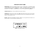
RECEIVER FRONT PANEL MODULATION - Indicates the modulation (audio level) of the incoming signal - see transmitter manual for proper adjustment of transmitter "MIC LEVEL" or "GAIN." The -20 lamp should flicker, or stay lit as you speak into the microphone. The 0dB lamp is a "peak" indicator showing that the audio gain in the transmitter is set too high. It is normal, however, to see an occasional flicker of the 0dB lamp. POWER OFF-ON Switch - This slide switch turns the power off and on.
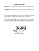
RECEIVER REAR PANEL ANTENNA terminal - A standard BNC connector compatible with the supplied A-185BNC telescoping antenna. 12 VDC INPUT - Connect the power supply here - the CH-12 AC adapter is supplied with the receiver for powering the unit from a 110V AC source. The receiver may also be powered from 12 volt DC sources using the correct plug (Switchcraft S-760 power plug); the center pin on the receiver jack is positive (+).
SYSTEM SETUP AND OPERATION 1) CONNECT POWER CORD - On your external power source, be sure the center pin is positive(+). 2) ATTACH AND EXTEND THE ANTENNA 3) CONNECT THE AUDIO CABLE 4) SET FRONT PANEL SWITCH TO "ON." Check to see that the red POWER LED lights up. 5) ADJUST TRANSMITTER "GAIN." This is perhaps the most important step in the set up procedure.
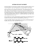
ANTENNA USE AND PLACEMENT Connect the antenna to the rear panel jack. Extend the antenna fully. Position the antenna so that it is not touching or within 3 or 4 feet of large metal surfaces. It is also good practice to position the receiver so that there is a direct "line of sight" between the transmitter and the receiver antenna. A wireless transmitter sends a radio signal out in all directions. This signal will often bounce off nearby walls, ceilings, etc.
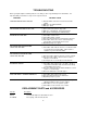
TROUBLESHOOTING Before going through the following chart, be sure that you have a good battery in the transmitter. It is important that you follow these steps in the sequence listed. SYMPTOM POSSIBLE CAUSE TRANSMITTER BATTERY LED OFF 1) External LED is turned off. Check internal slide switch. 2) Battery is inserted backwards. 3) Battery is dead. NO TRANSMITTER MOD LEVEL LEDs 1) Gain control turned all the way down. 2) Battery is in backwards. Check power LED.
SERVICE AND REPAIR If your system malfunctions, you should attempt to correct or isolate the trouble before concluding that the equipment needs repair. Make sure you have followed the setup procedure and operating instructions. Check out the inter-connecting cords and then go through the TROUBLE SHOOTING section in the manual We strongly recommend that you do not try to repair the equipment yourself and do not have the local repair shop attempt anything other than the simplest repair.
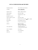
SR170 AC SPECIFICATIONS AND FEATURES Operating frequencies: 150 to 216 MHz crystal controlled Sensitivity: 1.0uV for 20dB SINAD 2.0uV for 50dB S/N ratio Signal/noise ratio: 96dB flat; 100dB A-weighted Squelch quieting: greater than 100dB AM Rejection: -40 dB (10uV to 0.
LIMITED ONE YEAR WARRANTY The equipment is warranted for one year from date of purchase against defects in materials or workmanship provided it was purchased from an authorized dealer. This warranty does not cover equipment which has been abused or damaged by careless handling or shipping. This warranty does not apply to used or demonstrator equipment. Should any defect develop, we will, at our option, repair or replace any defective parts without charge for either parts or labor.