INSTALLATION and STARTUP GUIDE SPNTWB Trio Conference Interface Wideband Bridging Software and Hardware Installation and Setup IMPORTANT See page 14 for Minimum Setup Requirements Visit the ASPEN Support web site: www.lectrosonics.com/aspensupport/ Also link from the home page: www.lectrosonics.com Fill in for your records: Serial Number: Purchase Date: Rio Rancho, NM, USA www.lectrosonics.
SPNTWB 2 LECTROSONICS, INC.
Installation and Startup Guide Important Safety Instructions This symbol, wherever it appears, alerts you to the presence of uninsulated dangerous voltage inside the enclosure -- voltage that may be sufficient to constitute a risk of shock. This symbol, wherever it appears, alerts you to important operating and maintenance instructions in the accompanying literature. Please read the manual.
SPNTWB Introduction The SPNTWB combines the circuit board assemblies from the SPN812 and SPNCWB in a 2RU chassis to provide a complete, stand-alone component for telepresence and audio conferencing systems. The unit can also be used with additional ASPEN processors to add additional inputs and outputs. Setup and adjustments can be made using the control panel software or the front panel LCD interface. Inputs and outputs appearing on the LCD have been consolidated into logical groups to simplify navigation.
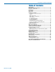
Installation and Startup Guide Table of Contents IMPORTANT.............................................................................1 Important Safety Instructions...............................................3 Inspection of the Unit.............................................................3 Introduction.............................................................................4 Front Panel..............................................................................6 Rear Panel...................
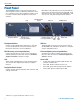
SPNTWB Front Panel The SPNTWB includes a front panel LCD and rotary style navigation control for adjustment without the need for a computer interface. The headphone output is used to monitor each final mix for diagnostics and system checkout. LCD Headphone Monitor Blue LEDs on the right side of the front panel indicate power status and communications through USB, serial and ethernet ports. The center white LED blinks to indicate an error, and glows during firmware updates.
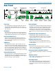
Installation and Startup Guide Rear Panel Cooling Fan Outlet Programmable Input and Output Ports Balanced Outputs Balanced Inputs Made In the USA Power Inlet RS232 Serial Port Ethernet Port Data/Audio Bus Ports Power Inlet The switching power supply will operate with line voltages between 100 and 240 VAC. The inlet socket is a standard 3-pin C14 type that accepts any cordset with a C13 connector.
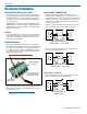
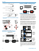
SPNTWB Hardware Installation Cables It is recommended to use lacing bars for cable strain relief when mounting in a rack. Use only professional audio cable with proper shielding – typically, two conductor plus ground/shield. Three wire cables should have the shield connected to the (–) connector at the source end of the cable. Retaining Screw (Do not overtighten) Two wire cables should have a jumper between the processor (–) input and ground. Source Caution: Do not overtighten the screws.
Installation and Startup Guide Audio Outputs Programmable Inputs The line outputs are a balanced differential configuration which can drive balanced or unbalanced inputs on other audio equipment with the wiring shown here. Programmable inputs are provided to enable external control over a variety of parameters. Each input can respond to a contact closure, a DC voltage source, or the variable voltage output from a potentiometer. The following illustrates common connections to the programmable input pins.
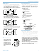
SPNTWB Crestron® and AMX® Port Wiring Diagram LED is ON when the programmable output is active +5VDC 1 TX 2 RX 3 4 ASPEN RS-232 GND 5 Port 6 7 8 9 Female jack 380 Ohms Programmable Output Pin LED is OFF when the programmable output is active +5VDC 380 Ohms Programmable Output Pin GND Male connector Relay is on when the programmable output is active External DC Voltage Source (<40VDC) 1N4001 or equiv.
Installation and Startup Guide Software Installation NOTE: Uninstall any previous version before installing the software. ASPEN Control Panel software can be installed from the disk supplied with each processor, or from files downloaded from the ASPEN Support web site. The third screen displays an option to select the desired installation. It is best to check all three boxes so the the USB driver, Control Panel and Help utility will all be installed. http://www.lectrosonics.
SPNTWB Software and Firmware Updates On ASPEN models with a front panel LCD, the firmware version is displayed on the Main menu screen. For all ASPEN models, the firmware version is displayed in the Control Panel program when connected to the processor. Firmware version Firmware Update Procedure Update Procedure 1) It is assumed that the USB drivers and ASPEN control panel software have been installed.
Installation and Startup Guide 5) Click on Next in the control panel and another page will open, allowing you to select the device to be updated. Highlight the device and click Next to proceed. 8) Do not disturb the USB cable connection during the update process. The firmware update takes up to 15 minutes to complete. Be sure the computer does not go into hibernation or sleep mode during the update process.
SPNTWB Stacking Multiple Units If Slave units are not powered up when the Master unit boots up, the Slave may not be detected for several minutes. It is good practice to turn all units on simultaneously or turn on Slave units before turning on the Master unit. The available processors will appear in a “stack” in the control panel. The Master unit details will appear at the top, with Slave units below it appearing in the order that they are connected with the cable connections to the ASPEN port jacks.
Installation and Startup Guide Output Sources Acoustic Echo Canceller Click on the Output Source tab. These assignments pass the matrix mixes to the outputs. Click on the Acoustic Echo Canceller tab at the bottom of the conferencing screen. The AEC (acoustic echo canceller) can be enabled on any or all of the conference interfaces. Strip chart metering indicates the performance of the AEC on each interface. Select the desired interface to display, or to display all four simultaneously.
SPNTWB The Signal Flow Screen Select the Signal Flow tab. This comprehensive, intuitive interface allows settings to be made through the entire signal chain. Double left click and single right click actions open setup and status dialogue boxes. 16 The view may be panned or zoomed as needed. Hold down the CTRL key and press + to zoom in. Hold down the CTRL key and press - to zoom out. The mouse scroll wheel can also be used. Hold down the CTRL key and turn the mouse wheel up or down to zoom in or out.
Installation and Startup Guide Unused crosspoint columns can be hidden and unhidden by highlighting a range of Mixes across the top, followed by a right click and selection of the desired state.
SPNTWB Using the LCD Shortcut Buttons The LCD can be used to check current settings or make adjustments without using a computer interface. • LCD Backlight Toggle: Press both the LEFT and RIGHT buttons to turn the backlight on and off. • Emergency Mute (panic button): Pressing the UP and DOWN buttons together will mute all outputs to remedy situations such as runaway feedback.
Installation and Startup Guide After selecting the mode and/or changing the passcode, select SAVE with the rotary control and press the center switch to save the settings. A progress bar will appear as the settings are saved. Navigating Individual Settings The following example illustrates the structure of the LCD screens used to set up the processor. Select a category from the Main Screen. Press the LEFT (9:00 o’clock) button to return to the previous screen.
SPNTWB LCD Categories and Settings INP (Input) PRE (Presets) • Recall Settings • Store Settings • Reset to Defaults • Run on Recall Macro • Powerup Defaults • Protected Settings • Input Levels • Mic/Line Input Setup • Conference Input Setup • Test Sig Input Setup SYS (System) • Compressor Setup • • Noise Reduction Setup • ADFE Filter Setup • EQ Filter Setup • Input Group Setup MAT (Matrix) Conferencing Setup Telephone Interface DTMF and Dialing Codec 1 Interface Codec 2 In
Installation and Startup Guide Network Setup Web Browser Interface The SPNTWB is IP addressable over an ordinary Ethernet network. The use of DHCP to configure the network interface is recommended for easy setup. Using the front panel LCD, navigate to SYS>Network Settings and set Use DHCP to YES. A simple interface is provided to communicate directly with the processor through a network using the HTTP port and a standard browser.
SPNTWB Service and Repair If your system malfunctions, you should attempt to correct or isolate the trouble before concluding that the equipment needs repair. Make sure you have followed the setup procedure and operating instructions. Check the interconnecting cables and then go through the Troubleshooting section in this manual. We strongly recommend that you do not try to repair the equipment yourself and do not have the local repair shop attempt anything other than the simplest repair.
Installation and Startup Guide FCC PART 15 COMPLIANCE INFORMATION This equipment has been tested and found to comply with the limits for a Class A digital device, pursuant to Part 15 of the FCC Rules. These limits are designed to provide reasonable protection against harmful interference when the equipment is operated in a commercial environment.
LIMITED THREE YEAR WARRANTY The equipment is warranted for three years from date of purchase against defects in materials or workmanship provided it was purchased from an authorized dealer. This warranty does not cover equipment which has been abused or damaged by careless handling or shipping. This warranty does not apply to used or demonstrator equipment. Should any defect develop, Lectrosonics, Inc. will, at our option, repair or replace any defective parts without charge for either parts or labor.